On this page I have listed instructions for making several different Octosory Boards. There are four methods shown that will produce a beautiful oak or other hardwood board that should last for decades and may be passed down from generation to generation. It will take a few days (or longer) to make, but the final result will be something you will be proud to own. Some woodworking skills are required, but it is not too difficult and is a great way to learn a new skill.
If that is not something you want to tackle right now but you are interested in playing the game Octosory, I have a much simpler method of producing a smaller board out of foam poster board. I will show these directions first. You may click on any picture to enlarge it.
Make an Octosory Board with a foam poster board base.
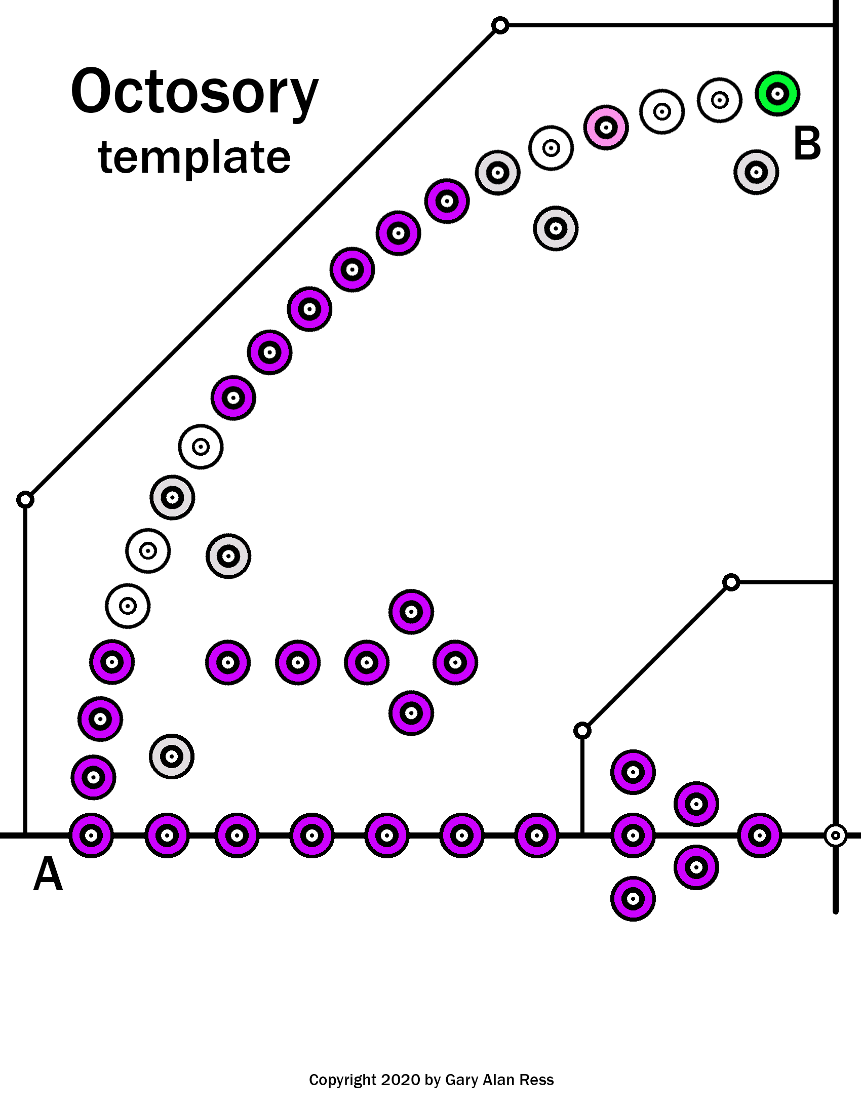
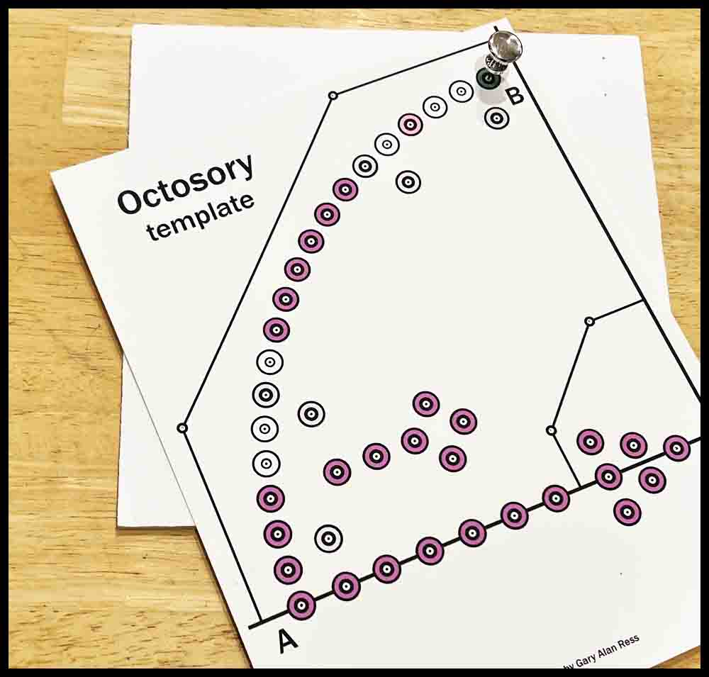
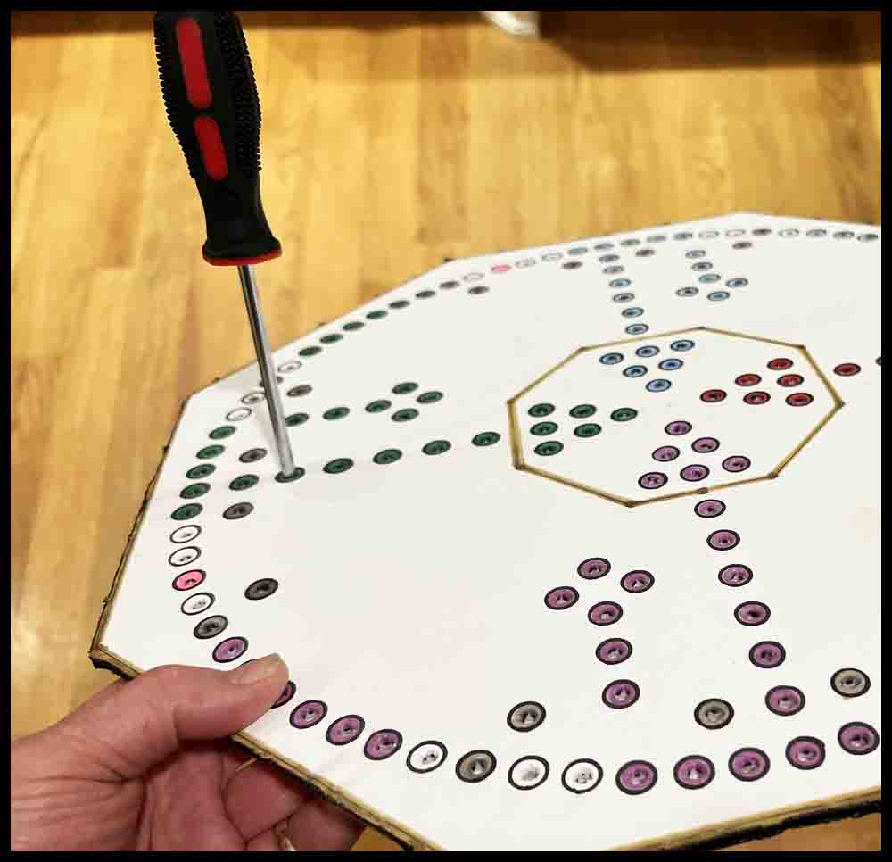
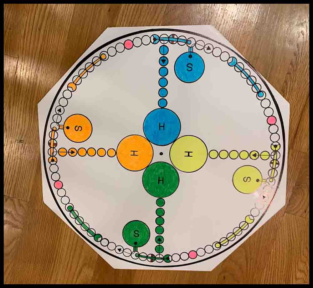
As I did for my Aggarv8ion game, I have drawn up a template that can be printed on a piece of card stock and used to transfer hole locations to a piece of foam poster board. This game will be a few inches smaller than the full size wooden board shown further down this page. For game pieces, instead of using marbles, we will make some rockets out of screws that will slip into the holes pierced in the poster board. Click on the green link to display the rules. The template is on the right below:
Before reading the instructions, take a look at the next few paragraphs. When using foam poster board to make any of the four games listed in the first paragraph these tools will be used.
Different tools for piercing holes in foam poster board.
Click the pictures for a bigger view.
A. The first tool in the top picture is a push pin. It works great for piercing the initial holes through templates made out of cardstock used for making Octosory and Aggarv8ion. For Rainbow Raceway and Orbital Summation, push pins are used for the initial mark in the image of the game that was printed out.
B. The metal scribe shown below the pushpin is a great choice to use as a center punch on wooden bases that have been pre-marked with a push pin. The enlarged view of the tip is just to show this particular tool. The important part is the nice sharp point.
C. The third tool from the top is a homemade scribe I have used for years. This is the perfect size (1/8″ diameter) for opening up the small holes initially made in all of the foam boards. The sharp point assures the hole location is picked up accurately. Search for a similar pointed awl or scribe in a hardware store or use a screwdriver like the small one described below in D.
D. The Phillips screwdrivers offer three different sizes for piercing clearance holes. The small one (.120 dia.) can be used the same way as the homemade scribe above. The point is small enough to pick up the initial small holes made in the poster board, although it might be helpful to grind more of a point on it with a belt sander.
E. Two games will use a slightly smaller diameter piercing tool. Orbital Summation and the smaller version of Rainbow Raceway use #6-32 screws to make the game pieces. The tools shown in the lower picture were both made from drill bits found around the garage. The shorter drill uses a wire nut for a handle. On the longer carbide drill I found a plastic drywall insert to use as a handle. Both handles are taped on with duct tape.


Steps for making a foam poster board game.
1. Click the image located above right. Download and printout the template on a piece of heavy cardstock.
2. Use a pushpin to punch a tiny hole in each circle on the cardstock template. To make this easier to do, place the image over a scrap piece of poster board or cardboard.
3. Open up the four inner and outer edge circles with a 1/8″ scribe or similar tool. (See the section above on piercing tools.)
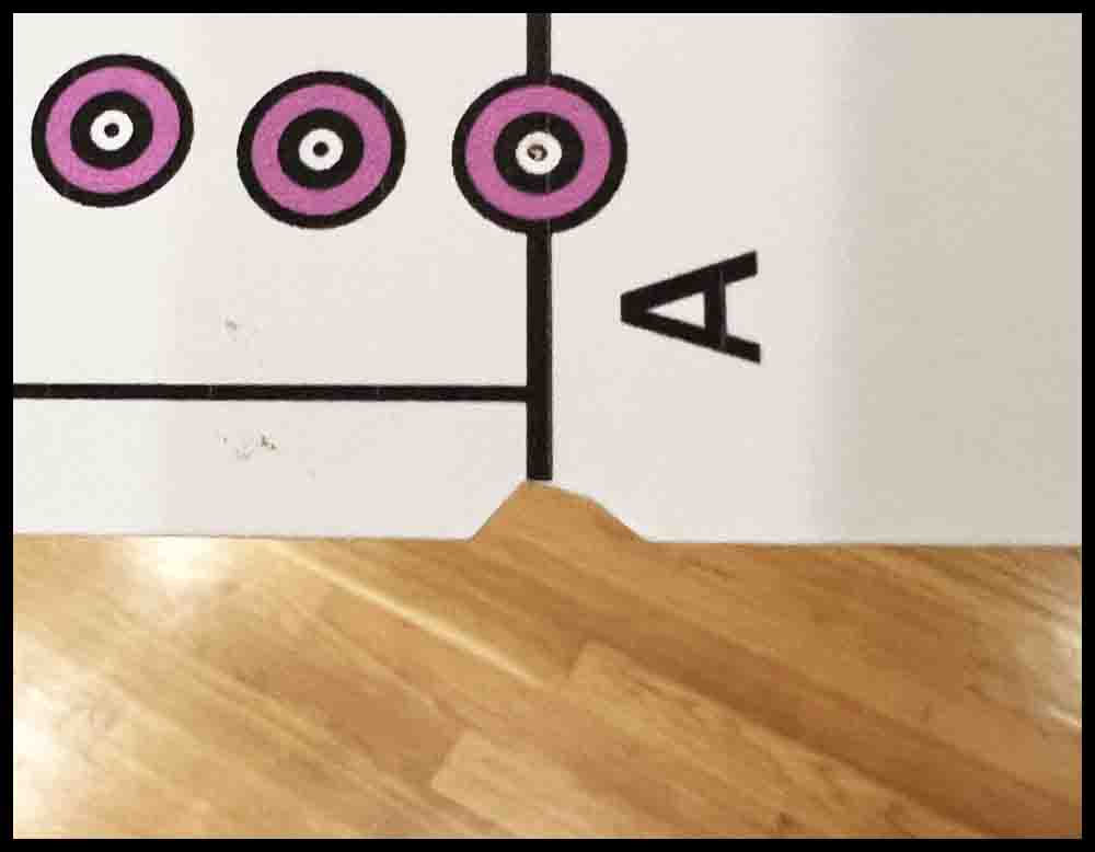
4. Use scissors to cut away the paper at the ends of Lines A and B so that the ends are exposed.
5. Stick two pieces of tape over the center hole, then flip the template over and re-pierce the hole with a push pin. This will strengthen it.
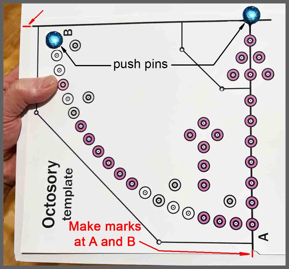
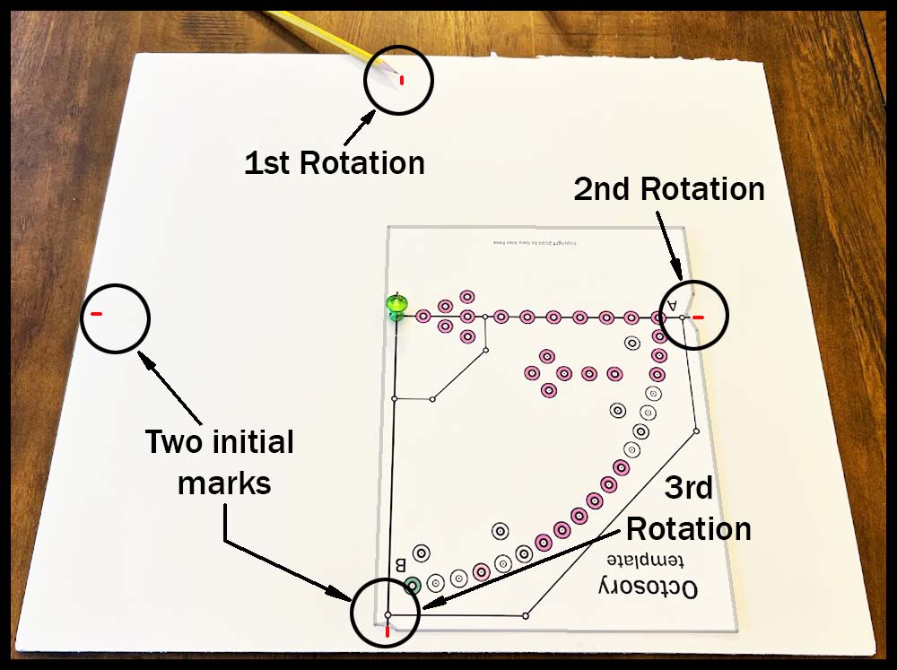
6. Place the image on a piece of poster board that is at least 18″ square. The image should be parallel to the edge and approximately 1/2″ from each edge as shown in the first picture below. Place a scrap piece of poster board or cardboard underneath so the push pins will go all the way in and not stop on the table. Carefully insert a pushpin into the center pivot hole, then place another push pin through the green hole next to Line B. This will help relocate the template after moving it in the next few steps.
7. Hold the template firmly in place and draw a small line at the end of Lines A and B. Draw these lines lightly because they will be erased later.
Steps 8-10 will set up rotation marks and check the accuracy of the template. Sometimes printers can distort images, causing small errors when the template is rotated around the board. These errors will get bigger each time the template is rotated.
8. Remove the locating pushpin from the green hole. Do not return it to the board until Step 11. Rotate the fixture 90 degrees clockwise until Line A lines up with the mark made at Line B in the last step. Make another small mark at the new position of Line B. Repeat this process again, making a third mark at the end of Line B.
9. Rotate the template for a third time, again locating Line A next to the third mark just made in Step 8. Line B should be close to the original mark made at the end of Line A on the bottom of the board. Make a final mark at the end of Line B.
Stick two pieces of tape over the center hole, then flip the template over and re-pierce the hole. This will strengthen it.
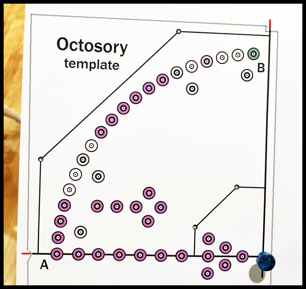
The template is ready to position on the poster board. It will go in the lower left quadrant of the board the first time.
10. If the final mark lines up pretty close to the original mark, Proceed with Step 11. If there is a difference (at least 1/32″) between the marks, either from rotating too far or not enough, then follow directions A to D below. The error should be minimal after performing the corrections.
For example, after rotating the template three times (Step 9), suppose the final mark at Line B is 3/32″ short of matching up with the original Line A mark. To correct this, the template will have to be rotated 1/32″ more each rotation. New rotation marks will be made to accomplish this task:
A. Start by going to the mark on the left side of the board made at the end of Line B when the template was in the original position. Make a new line parallel to that mark and 1/32″ above it. Erase the first mark.
B. Go to the second mark at the top of the board and repeat this process, making the new mark 2/32″ (1/16″) past the original mark. Erase the old mark.
C. Change the third mark, making a new line 3/32″ past the original. Erase the old mark.
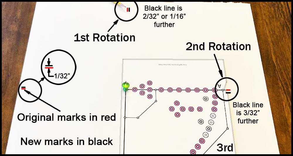
D. Rotate the template and match the end of Line A with the new third mark just made. Line B should now be fairly close to matching the position of the original mark at the bottom of the board at Line A. A little mismatch won’t change the appearance very much, so if it is off a little don’t fret about it too much. Move on to Step 11 to transfer the hole locations.
Final Steps
11. Return the template to the original position. Replace the push pin in the green hole used before for locating the template. Tape down the template in a couple of places so it won’t move.
12. Transfer all the holes pierced in Step 2. Use a pushpin to do this, inserting it into each tiny hole and shoving it down vertically into the poster board. Do not pierce the foam poster board where the 1/8″ edge holes are located (Step 3). Trace these 1/8″ holes on the inner and outer edges with a pencil. Use very light pressure as you may want to erase these circles after connecting them together in Step 14.
13. Repeat this procedure, rotating the template 90 degrees three times, lining up the template with the marks made in Steps 8 and 9. Tape down the template in each quadrant and transfer the holes with a push pin.
14. Remove the template. Connect the edge circles using a straight edge and a pencil or permanent marker. These lines will form the outline of the inner and outer edges.
15. Cut out the final shape of the game board with a razor knife and straightedge.
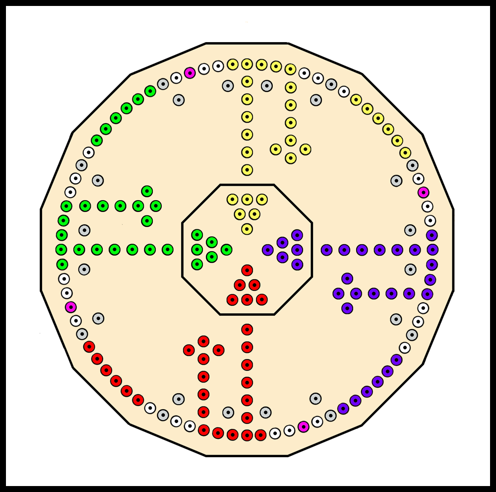
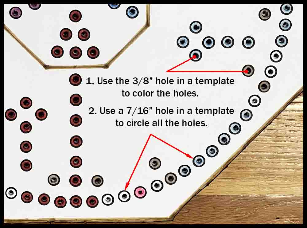
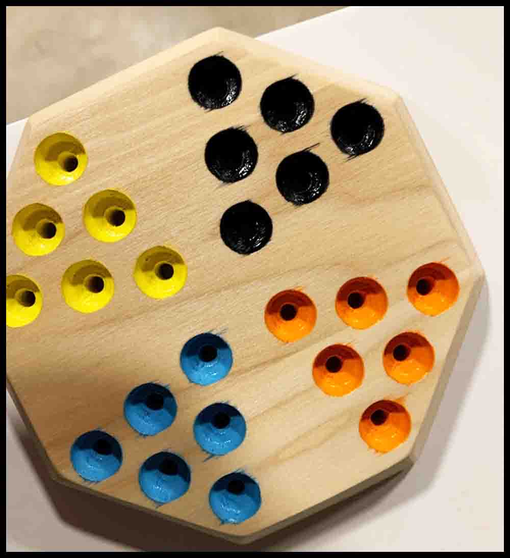
16. Use the 3/8″ circle on a drafting template and look at the first picture below as a guide to filling in the correct holes with colors. The easiest way to do this is first trace a line around the inside of the drafting template circle with a permanent marker that is the proper color, then come back and fill in the rest of the hole. The holes in the WarpDrive Bubble should be silver or light gray, and the SolarFlares are a shade of pink. Color the three remaining groups of holes any color you desire. The neutral holes will be white and will just require a 7/16″ black circle to be drawn around them. Use the 7/16″ hole on the drafting template to trace the black rings around all of the holes. A medium point permanent marker will work fine.
17. Open up all the tiny holes with a 1/8″ diameter tool, then repeat with the 3/16″ tool you choose for piercing the holes to their final size.
Stick some small felt pads to the bottom. Decorate as desired!
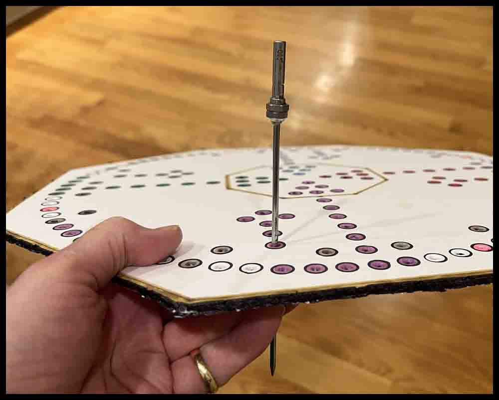
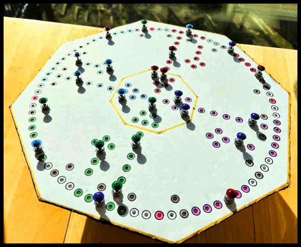
You will need to make some game pieces or “rockets” to play the foam poster board version of Octosory. Click the button on the right to see how.
How to make a beautiful Octosory game board out of hardwood
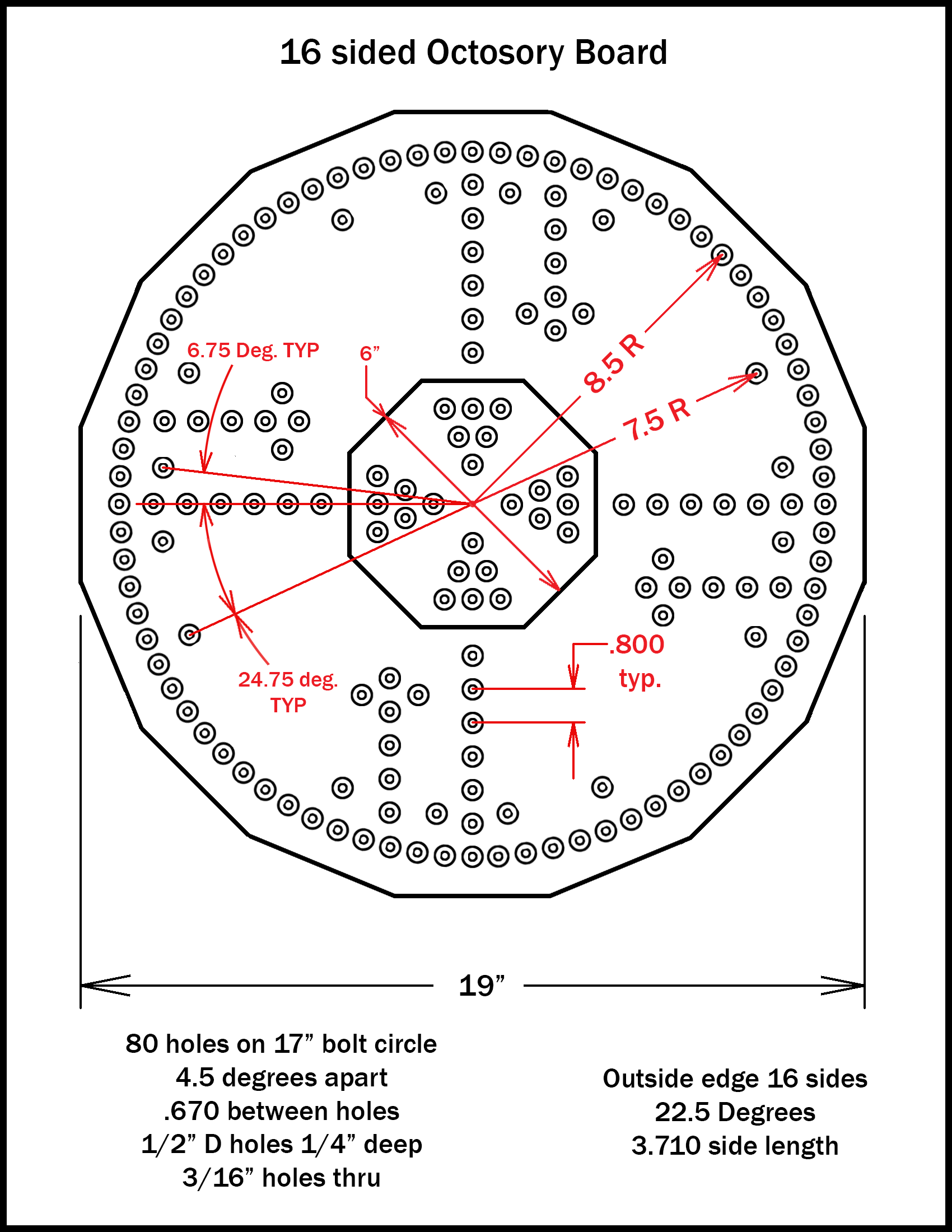
There are four basic methods for making a wooden Octosory board. Methods 1 and 2 will produce the biggest board as shown on the blueprint:
Method 1: Layout the hole locations directly onto a board. Directions for drilling, counterboring holes and finishing the board are included in this section regardless of which of the four methods are used to lay out the hole dimensions.
Method 2: Make a plexiglass drill fixture to layout all the holes in one section, then rotate the fixture three times to transfer all the holes. This method is perhaps the best for making multiple boards. You will only have to draw the hole locations for one quadrant, one time.
Method 3: To lay out all the holes use the same paper template that was used above in the first section where a foam poster board was made . This will produce a board 17″ across and is perhaps the easiest method for making a wooden board. The template is reproduced below where Method 3 is detailed.
Method 4: Use a CAD program on a computer to design the board following the blueprint.
Method 1: Follow the blueprint to lay out the hole locations.
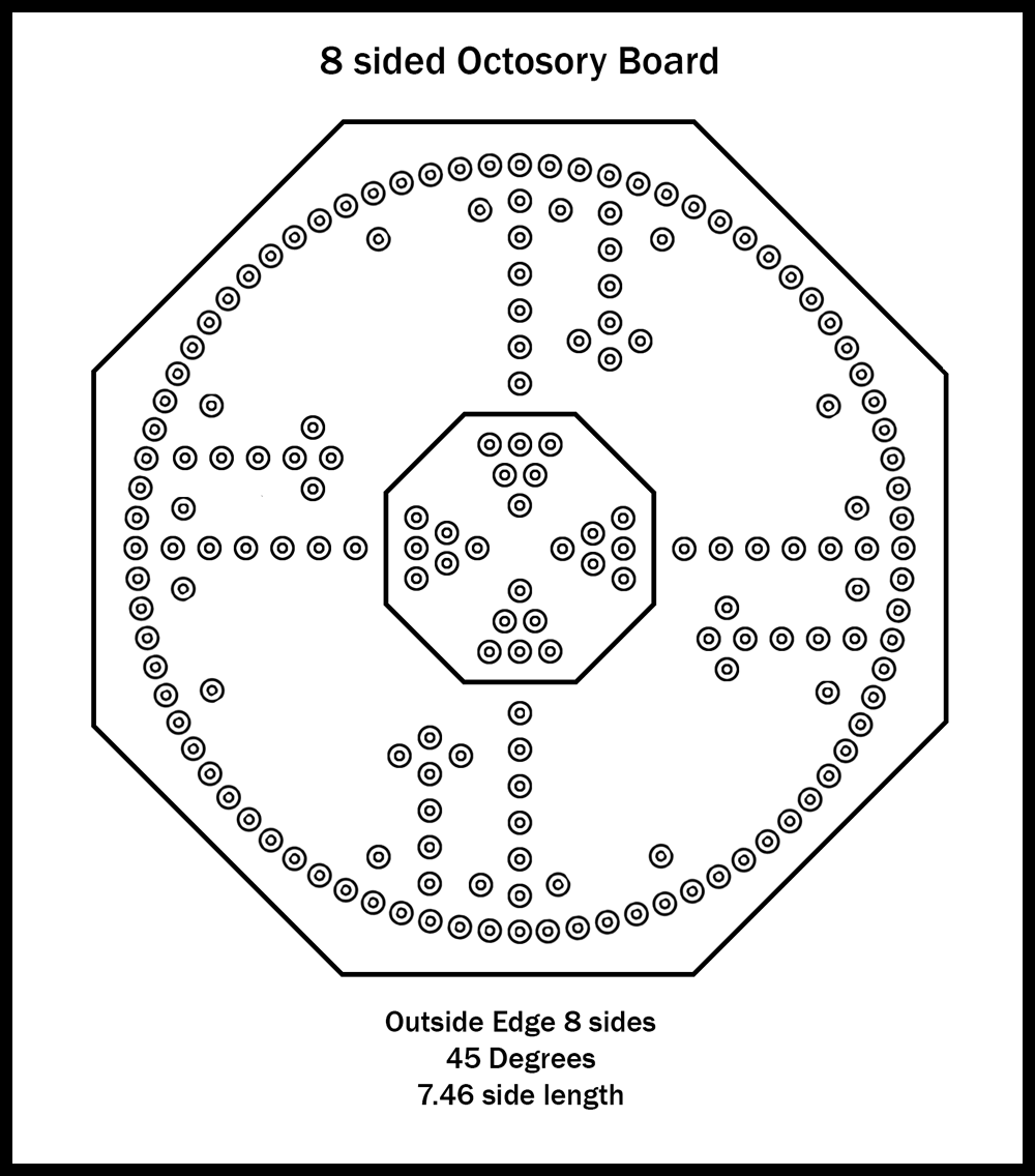
Explaining some of the dimensions on the Blueprint.
You may look at the dimensions of 6.75 or 24.75 degrees and think “This guy is crazy!” Well, the next four paragraphs explain why the figures are included in the blueprint. You may skim past those four paragraphs to the section Getting Started if you like.
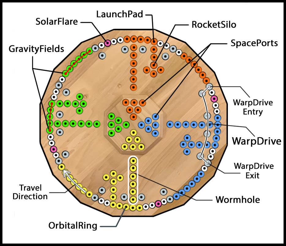
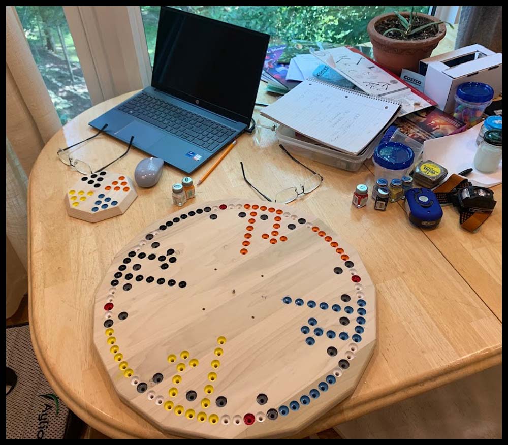
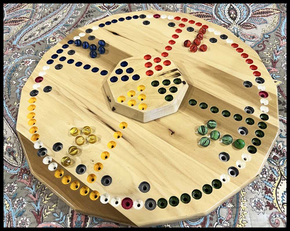
The only reason those angular dimensions appear as being extremely precise is because they show different holes’ relationship with each other by using degrees. The first and last hole of the WarpDrive Bubble, illustrated by the silver circles on the inner radius, should be located between the fifth and sixth holes counted in either direction away from the first hole in the Wormhole on the main ring of holes. The sixth hole, traveling in a clockwise direction, is where a player will enter or exit the WarpDrive Bubble. Look at a picture of the board above if this is confusing.
For example, looking at the pictures, you can see two groups of WarpDrive Bubble holes on the left side of the board . The first hole in the lower of the two WarpDrive Bubble groups is shown to be located 24.75 degrees from the line of horizontal circles above it. For this example lets call the first hole of the Wormhole hole zero. The first hole of the WarpDrive Bubble, as far as the angle goes, is located on a line originating from the center of the board extending between the fifth and sixth holes away from hole zero on the main hole circle.
Here’s how the correct angle was figured: There are 360 degrees in any circle and 80 holes located on the main circle in this game. Divide 360 by the number of equally spaced holes on the main hole circle. 360/80 = 4.5 degrees. Continuing, 4.5 degrees x 5 = 22.5. Since the hole is located between the 5th and 6th hole we have to add on the result of 4.5 degrees / 2 = 2.25. Adding 2.25 to 22.5 equals 24.75 degrees.
When making the game you will not be using protractors to lay those holes out with precise angles. Instead, after marking the positions of the 80 holes on the outer circle, you will just draw a line starting from the exact center of the board extending outward between the correct holes. (5th and 6th holes from the Wormhole holes in the example above). The spot where the line intersects the smaller radius (7.5″ in these examples) is where the first hole of that WarpDrive Bubble is located.
Getting started
You can adjust all of the dimensions to make a slightly bigger or smaller board as long as you keep everything in the same relationship when scaling the drawing up or down. Read all the directions and look at the pictures before starting the project so you have a good idea of what you will be doing.
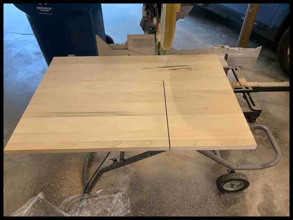
1. The first step is to cut your board in the shape of a square measuring 19″ on all four sides. It is important to cut the board square, each edge 90 degrees from the other. Small variances tend to multiply as the board making process progresses.
In Steps 2-3 an X and Y axis will be drawn across the board. The Wormhole holes will be drilled on these lines.
2. Measure one side of the board and make a tiny mark in the middle of that edge. Using a combination square, draw a line through that mark towards the center of the board. This line should be perpendicular to the edge. It will be the Y Axis. A drywall square can be used and will allow a line to be drawn across the total distance. If a 12″ combination square was used to make your line, it will not go all the way across the 19″ wide board. If this is the case, use another straightedge at least 20 inches long to accurately extend the line across the board. Measure the final line and mark the middle exactly with a pencil.
3. I suggest using a quality metal or plastic 45 degree triangle for this next step where the X axis will be drawn. The bigger the triangle, the more accurate the lines will be. Position the triangle so one side is exactly parallel to the original line and the 90 degree side is lined up with the mark made in the middle. Draw a line along the edge of the triangle, then use the straightedge to extend that line across the entire board width. (There are other ways of producing these lines but if the board is not exactly square this method will bypass that problem.) Ideally the board will be split into four equal quadrants or sections.
3A. Adding two more lines across the width of the board 45 degrees to the first two will make the job of laying out the holes easier and more accurate. If you will be making a plastic drill fixture as shown in the section that follows, there is no need for the 45 degree lines.
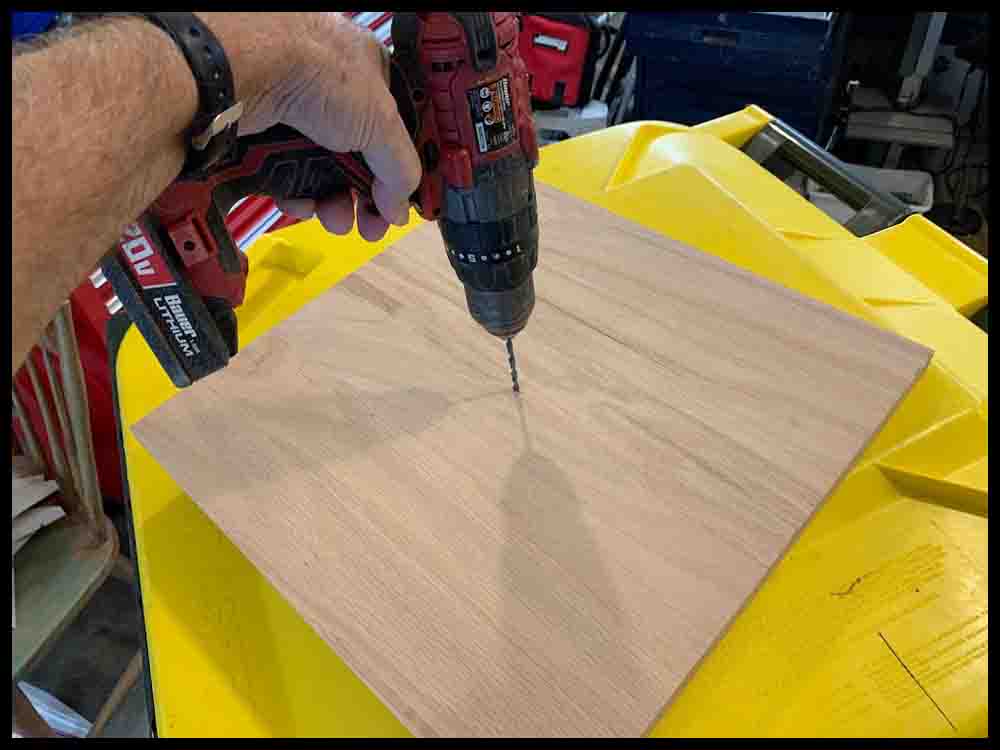
When you are satisfied with the initial layout, drill the middle 3/16″ hole. To insure accuracy, follow these steps:
1. First make a tiny “prick” mark at the intersection of the lines in the center of the board with a center punch and small hammer. Sometimes the grain of the wood will cause the center punch to veer off location a bit, so tap gently. Check the location constantly as the prick mark gets deeper.
2. When the prick mark is deep enough to allow a drill bit to accurately pick up the hole, use a small drill bit about 3/32″ to 1/8″ diameter to drill a hole through the board. Try to keep the drill perpendicular to the surface.
3. Open that hole up with a 3/16″ drill bit. I strongly suggest practicing first on a piece of scrap wood, preferably the same type as the board. Sometimes drills will wobble and grab, possibly ruining the hole shape. You should be able to insert the bottom of a 3/16″ drill bit or a #10 screw through the finished hole without much slop.
Make a Compass
1. You will need to make a “compass” to draw one big circle on the board to mark the edge and another two smaller circles for the hole radii. A 12″ wood school ruler will make a fine compass, but a thin piece of plywood or similar material will also work. The compass should be about 11″ or 12″ long and an inch or so wide. You may use this more in future projects.
2. Draw a line done the middle of the compass, then make a mark about 1/2″ from one end across that line with a pencil. This will be drilled through later with a 3/16″ drill for use as the center hole or pivot point.
3. Make three more marks 7.5″, 8.5″, and 9.5″ away from the first mark. Note: Read the directions all the way to the bottom. The 7.5″ dimension may be changed depending on the look desired.
4. Use a center punch and a small hammer to make a “prick” exactly at the locations of the four pencil marks.
5. Experiment on a piece of scrap material the same thickness as the compass you are making. Drill a small hole through the material about 1/16″ in diameter, then insert a pencil into the hole. Check to see how far the pencil point sticks out the other side. It should protrude just enough to draw circles on the board when the compass is rotated. If it does not go through far enough, drill a slightly bigger hole and try again. (This is why a small drill bit is used first.) When you are satisfied with the size drill you will need, drill all four holes in the compass where the prick marks are. Use a 3/16″ drill to open up the single hole located at one end. This will be the pivot point for swinging the compass in a circle.
Shape the Board
1. Take the compass you just made and connect it to the board surface by slipping a #10 screw or the bottom of a 3/16″ drill bit through the compass pivot hole and the hole in the center of the game board. It should slip in without a lot of slop.
2. Draw a circle by inserting a pencil through the hole located 9.5″ from the pivot hole. Hold the pivot pin firmly and straight up and down, perpendicular to the board surface. The finished 19″ circle should just come to the edge of the board in four places. We are now ready to cut the final shape of the game board.
As a final check of the X and Y axis lines, measure the diagonal distance between the points where the axes intersect the big circle that was just drawn. Each of the four diagonal distances should be equal. If they are not, recheck the X and Y axis relationship with a right angle triangle. Either the angle is not 90 degrees or the pivot hole is slightly elongated resulting in a slightly inaccurate big circle.
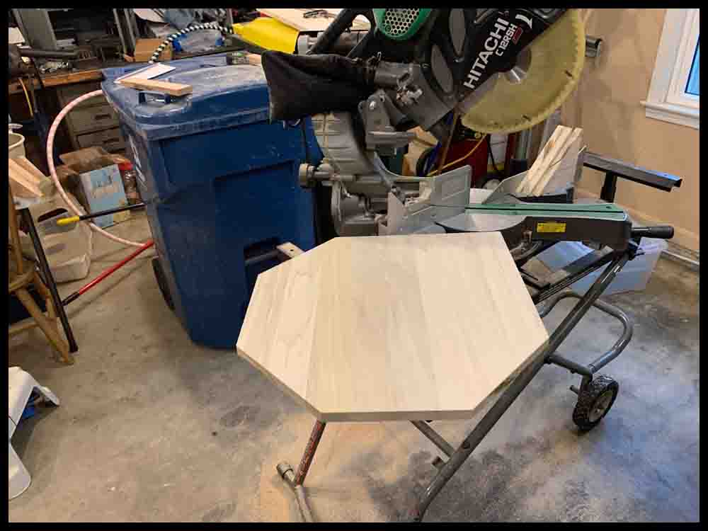
This has been said before, but it will be much easier and more accurate to use a 12″ sliding miter saw to make your cuts. You can find inexpensive ones for under $300. If you are going to get serious about doing future wood-working, this will be one of the best purchases you can make. Get a stand for it, too.
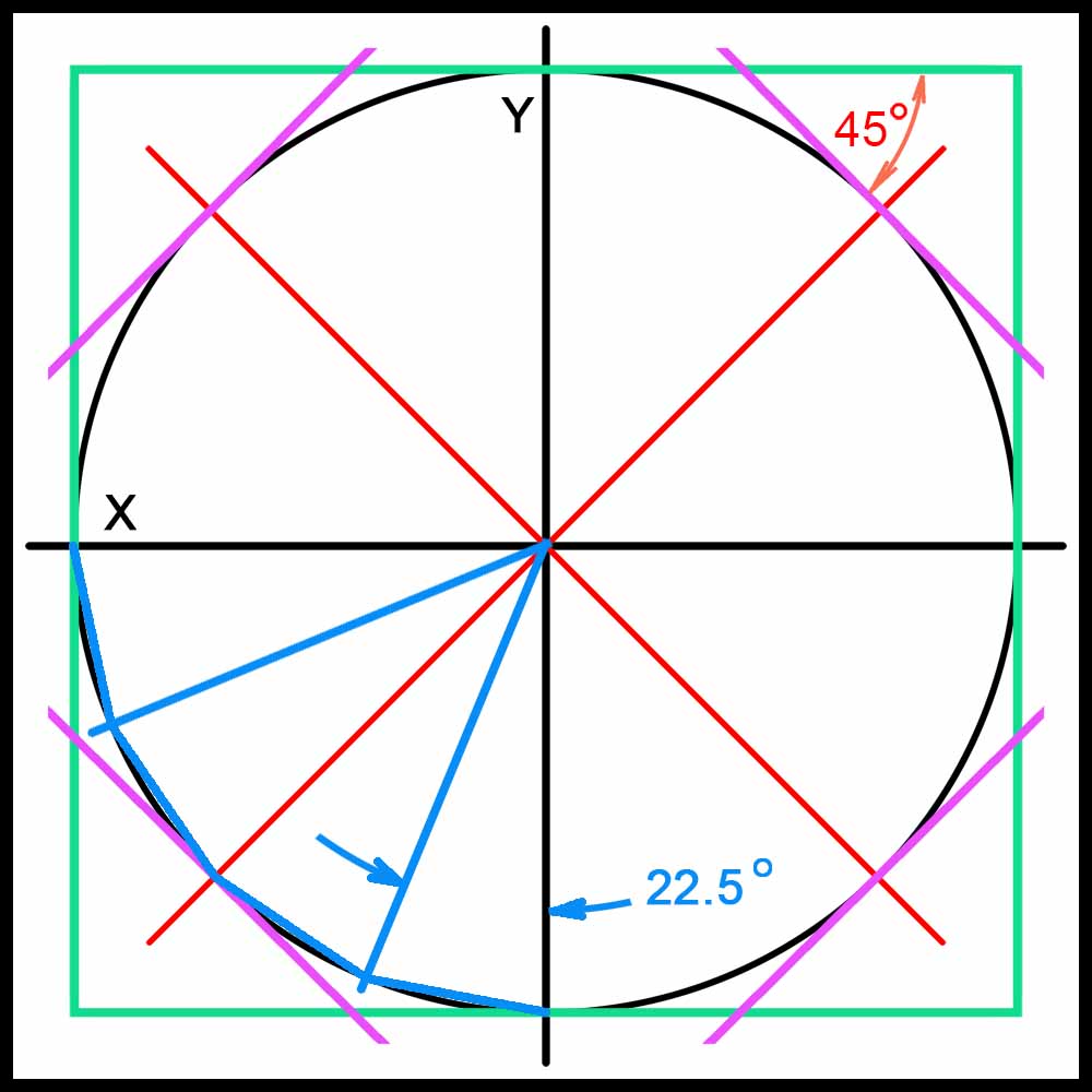
3. Use a combination square and a sharp pencil to mark lines 45 degrees to the edges of the board and tangent to the circle you just drew (purple lines in the drawing below). Make these lines using the X and Y axis drawn earlier as a guide. These lines will mark four of the eight edges of an eight-sided board.
4. Cut the board along the lines you drew with either a power miter saw or circular saw. Sand the edges and smooth the board before going further. If you prefer a sixteen-sided board, lay out equal lines 22.5 degrees apart around the circle. This may get confusing if you haven’t done anything like this before. See the blue lines in the drawing below.
In the drawing on the right you can see the original black circle drawn. The 4 board sides are shown in green. After adding the purple lines, the board has 8 sides. A sixteen-sided board is represented by the blue lines in the lower left quadrant.
Lay out and drill the holes
1. Following the blueprint, use the compass to draw a circle with a radius of 8 1/2″. Try to draw it lightly with a sharp pencil. You want to see it clearly but remember that you will be removing the pencil circle later with an eraser and sandpaper.
2. By drawing the 45 degree lines earlier in addition to the X and Y axis, you now have a more manageable area to evenly space out the holes. The holes are 4.5 degrees apart, so you will need 10 equal spaces in each of the eight sections. You can use a good scale and a set of dividers to help keep these spaces equal. Make a light line at each hole location with a pencil.
3. After you are satisfied with the accuracy of the hole locations in the outer circle, use the compass again to draw a circle with a radius of 7.5″ for the WarpDrive Bubble holes. Locate the four FastTrack holes as indicated in the blueprint.
Note: This 7.5″ radius is going to produce a board as shown on the blueprint and other pictures above. The radius may be changed as desired. In the directions above, where the foam poster board game is made, the template shows the first inner hole of the Wormhole on the same radius as the WarpDrive Bubble. Either way will result in a nice looking game.
4. Finish laying out the rest of the holes for the RocketSilo and Wormhole. Make the holes .8” apart (slightly less than 13/16″). Remember, this dimension is not critical; it is just one way of doing it. The design of the Dungeon (starting position) may be customized as desired. Just be sure it is adjacent to the proper hole on the outer rim.
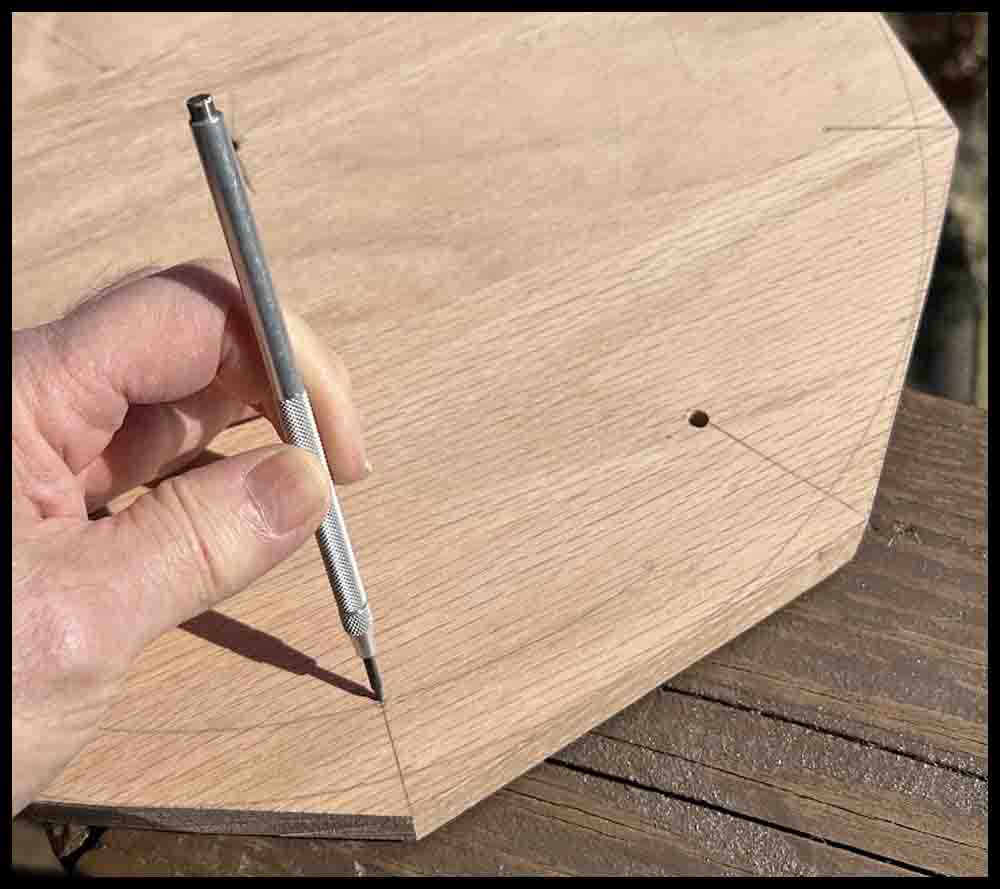
5. Once all the hole locations are determined and marked, use a center punch or scribe to make the initial “prick” that will be used for drilling the holes. Use a small hammer to make the prick mark deep enough that a small drill bit may be used to accurately start the hole.
Before drilling any holes, spray a coat of polyurethane on the board. This is discussed further down the page.
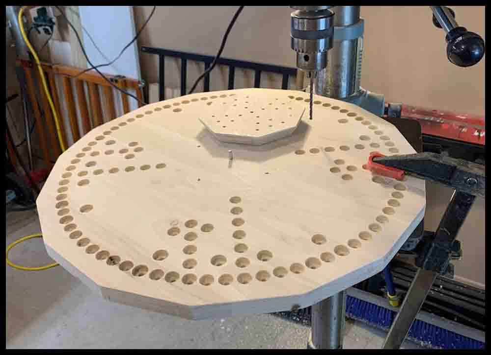
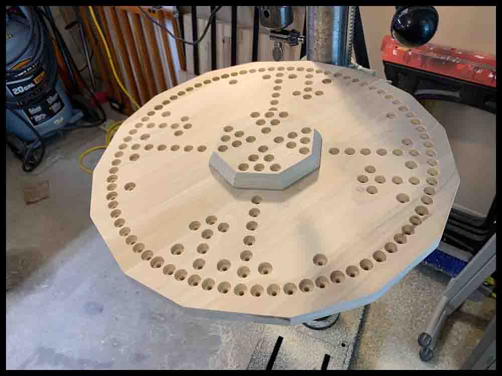
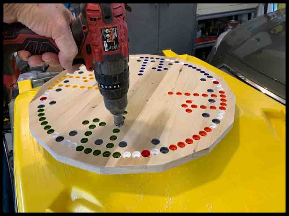
6. Start all the holes with a small drill bit (close to 3/32″ diameter) at least 1/8″ to 1/4′ deep. Switch to a 3/16″ drill bit and drill the holes all the way through the board. A 1/2″ spade drill will be used to counterbore the holes after making the SpacePort.
Before counterboring the holes, make the SpacePort as described in Step 7 below so that all the holes can be uniformly counterbored at the same time. The Fortress is made separately and screwed on after both pieces are finished. If you do not want to make this separate top piece, just ignore the outside raised shape of the octagon on the blueprint and lay out the 24 holes on the same board as shown in the blueprint. It will definitely detract from the neat look of the board, however.
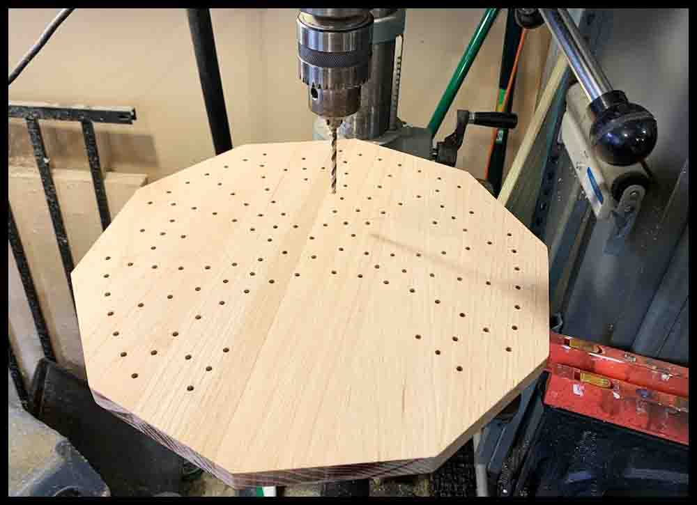

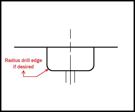
7. The SpacePort should measure about 6″ across, with the four groups of six holes laid out in a pattern similar to the pictures above on the right. Drill and counterbore the 24 holes. The remaining holes in the main board should also be counterbored at this time to maintain a constant depth. Remember, the way the marble fits is determined by the hole diameter, not the depth of the hole. See the two diagrams below.
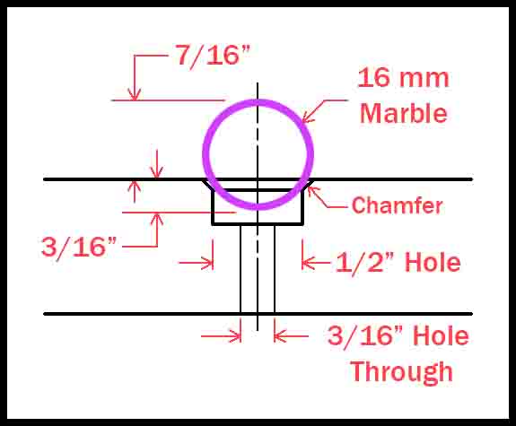
The diagram on the left shows the relationship between a 16mm (5/8″) marble and a 1/2″ hole with a small chamfer for breaking the edge. Enough of the marble is above the surface of the board to easily pick up and move. Any smaller hole than 1/2″and the marble would not be secure. If it was much bigger it would be hard to grasp. Repeating: Experiment in scrap wood with the drill you will be using to determine how the drill cuts before drilling on the game board.
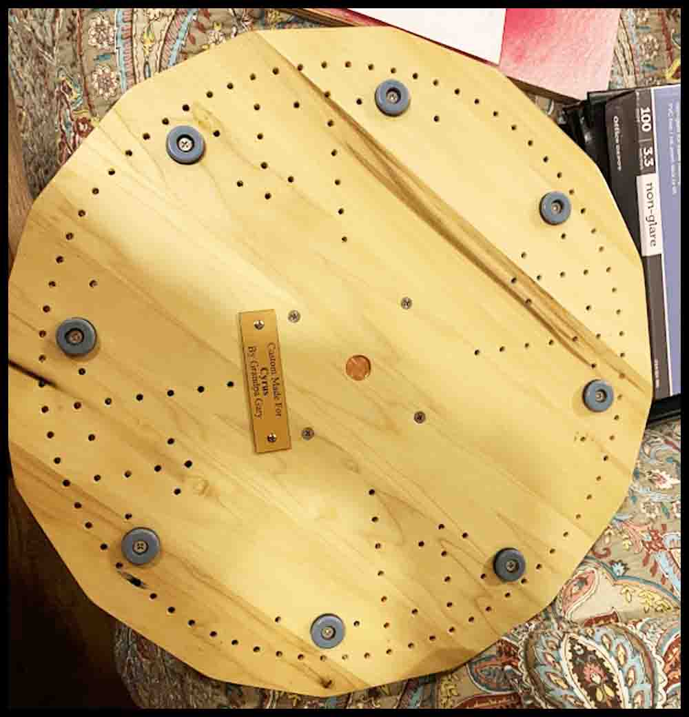
8. Drill a 3/16″ locating hole in the center of the SpacePort bottom. If you don’t want it to show on the top, then drill it about halfway through. In the pics above and below you can see the hole drilled all the way through. I will add a flag or statue in the middle hole eventually. This hole will be used to locate the Fortress in the center of the main board when the mounting holes are drilled. You will temporarily insert a 3/16″ (#10) machine screw, dowel pin, or the bottom of a 3/16″ drill bit through the bottom of the main board into the Fortress. If the oak board is 3/4″ thick, then a 1″ or longer screw will work.
8. Look at the picture on the right to see the four mounting holes for the SpacePort. (As for all the pics, click the picture to enlarge). They have to be located in the main board where they will not interfere with the 24 holes previously drilled in the Fortress for the game pieces.
9. Lay out the hole locations on the bottom of the main board. Mark their locations with a center punch, then drill through the bottom with the same size bit that will be used to drill the pilot holes in the Fortress for the mounting screws. (Experiment in a piece of scrap to determine what size pilot hole you will need. It just has to be a little smaller than the screw diameter so the screw thread will have something to bite into without having to turn the screws with a lot of force.)
10. To transfer and drill the mounting holes into the SpacePort, place it on the top surface with the center locating pin or screw in place. To ensure the SpacePort stays in the same position when removing and returning it to the board, make a small mark on each piece of wood next to each other. These marks can be lined back up together when returning the SpacePort to the same relative position after being removed.
11. Use some tape to securely hold the SpacePort block in position. It is difficult to get a clamp on it. Flip the main board over and use the same drill bit from Step 9 to transfer the mounting hole locations. Do this by by lowering the spinning drill bit through the previously drilled mounting holes in the bottom of the main board. Once the drill touches the bottom of the Fortress, drill down about 1/8″ further to mark the locations.
12. Remove the SpacePort from the main board. Lay it upside down and finish drilling the pilot holes in the bottom that were just transferred. They should go approximately 3/4 of the way through the thickness of the Fortress. Stop 1/8″ to 3/16″ from the top. (in other words, if you are using a 3/4″ thick board, drill the pilot holes a maximum of 5/8″ deep.)
13. Enlarge the mounting holes in the bottom board. The screws you use for mounting the Fortress will determine the hole size. The holes should be the same size or just slightly bigger than the screw diameter. This will locate the Fortress without the need for the 3/16″ locating pin.
14. After opening up the four holes, countersink them from the bottom deep enough for the screw heads to be a little below the wood surface. When determining the screw length, make sure they do not bottom out in the pilot hole when they are screwed all the way in. That could split the wood. Once these holes are finished, the 3/16″ center hole will not have to be used any longer to keep the SpacePort in position.
Painting the holes and finishing touches
Here’s a tip I learned from experience: Before drilling the holes, apply a coat of spray polyurethane to the top of the board and let it dry. I found out that when painting the holes the paint will bleed into the grain and mess up the finish a bit. You cannot sand these paint marks out, but after applying one coat of polyurethane before drilling, most of the surface will be sealed and less bleeding will occur. Countersinking the holes AFTER painting them will also clean them up nicer.
I gave each of the holes two coats of paint. Some of the holes needed three coats. Countersink the holes after painting, then use some sandpaper to smooth the whole board. I tried to apply polyurethane with a brush on the first game I made. BIG MISTAKE! Buy a few cans of polyurethane and spray it on with up to four coats. Follow the directions on the can in regards to drying times and when to lightly sand the finish.
Buy a pair of eight-sided dice and 16mm (5/8″) marbles to complete your game. Print off the rules and start playing!
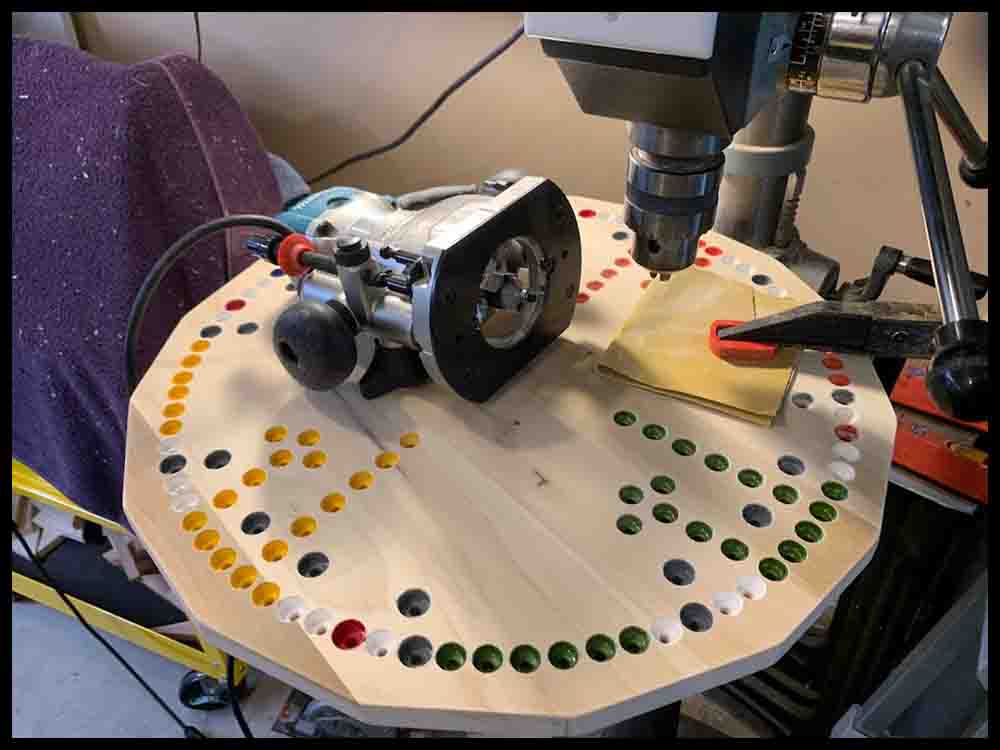
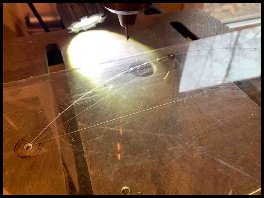
Method 2: Drill the holes with a drill fixture.
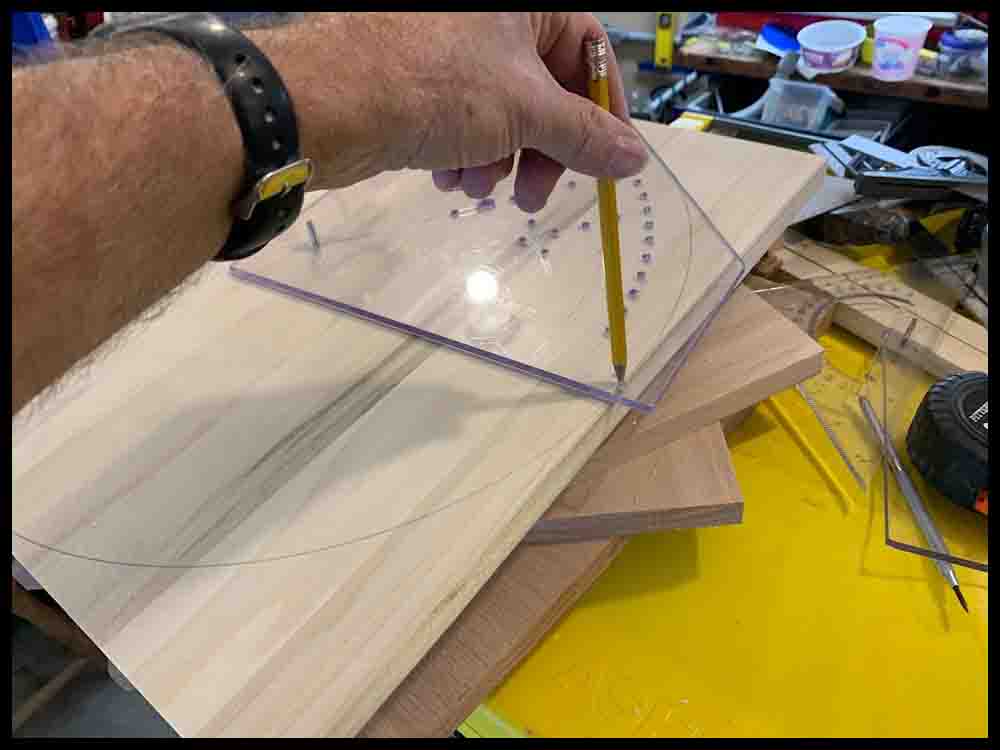
I knew I would be making several full size boards over time so I wanted a quicker way of drilling all of the holes accurately. There are 168 holes in the Octosory board. That’s a bunch of holes! I decided to make a drill fixture out of plexiglass that could be rotated to each of the four quadrants and used to transfer accurate hole locations. I bought a 3/16″ thick piece of Lexan (polycarbonate) plastic 12 inches square to make this reusable drill fixture. A piece 12″ square will cost around $10. I didn’t need to make a “compass” as described above in the first section of instructions. Instead I added little holes in the drill fixture in the right positions for marking big circles on the board. The next few paragraphs describe how to make the fixture and use it.
Try to be fairly precise when laying out the holes on the drill fixture. I used a precision drafting compass to lay out the main circles the holes would be located on and carefully marked the distance between the holes with a six inch scale, rechecking the accuracy from end to end of the fixture to make sure they were evenly spaced. Any hole that is slightly off location will be transferred to every board you make, in each of the four sections. Use a sharp metal scribe to etch tiny lines on the Lexan when marking the hole locations. I wore a head-mounted magnifying glass coupled with a flashlight as an aid to insuring the hole layout was precise.
Do NOT drill or layout the location of the bottom right hole at the end of the circle radius on the fixture. You can see where this hole position is located in the picture Step1. This hole will be drilled later in Step 2 as described in Steps 1-5 in the pictures below. This assures the distance to the holes on the ends of the fixture will be exactly on the same radius. This step will only be used once while making the first board. If multiple boards are made, you will just drill a 3/16″ hole in the center of the second board, then clamp the finished fixture in the lower left quadrant and start drilling. Both holes at each end of the circle radius will be located exactly on the radius and may be used for locating purposes as the fixture is rotated from quadrant to quadrant.
To mark each hole location before drilling holes in the fixture, use a small hammer and a center punch to make an initial “prick” on the surface. If the first prick appears to be off location a bit, you can “move” the prick a small amount in any direction by angling the center punch and gently tapping again with the hammer. Once you have the prick centered close to where you want it, use the hammer to make the prick mark deeper so the drill will pick it up accurately. For pilot holes in the Lexan, use a very small drill bit and drill all the way through the fixture. After drilling the pilot holes, go back and open the holes up with a 3/16″ drill.
The drill bits will get hot during use and try to melt the plastic, gumming up the hole and possibly ruining the fixture. Keep a small container of water close by to dip the drill bit into every 4 or 5 holes. By trial and error you can determine the length of time it takes to cool the drill bit.
You can now use the almost finished drill fixture to transfer the hole locations accurately onto the board, one section at a time.
IMPORTANT: Prepare the wood board as detailed above in the previous section. If the X and Y axis lines you draw on the board are not 90 degrees apart, or the center hole is not exactly at the intersection of these two lines, the drill fixture will not perform as designed in regards to accuracy. The only two lines that need to be drawn are those X and Y axis lines.
There are two factors involved in making an accurate fixture: First, the radius of the circular arc that the first and last holes of twenty holes are located on should be exactly the same. That is where the location pins are inserted each time the fixture rotates to a different position on the board. This will not be a problem because Steps 1 and 2 shown in the row of pictures below will insure the two locating holes are on the same radius. The factor that can cause errors, however, is what is described at the beginning of this paragraph. The X and Y axis lines must be 90 degrees apart, the center hole must be located at their exact intersection, and care must be taken when lining up the hole with the Y axis as shown in Step 2.
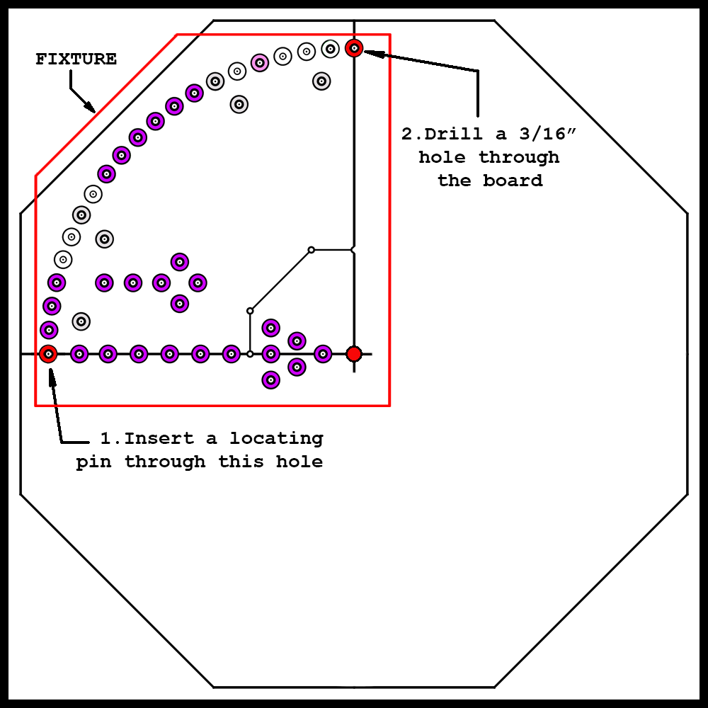
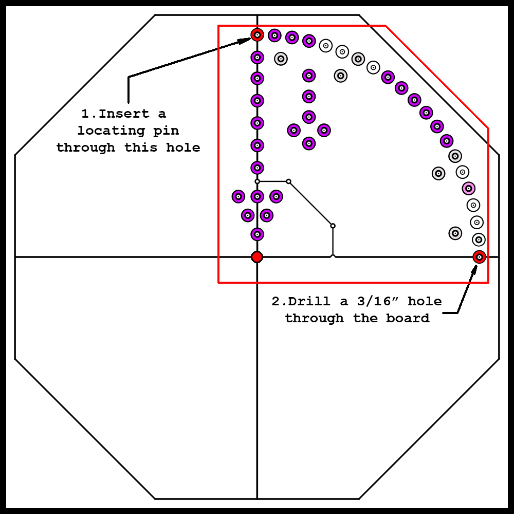
The five drawings below will help you make the drill fixture:
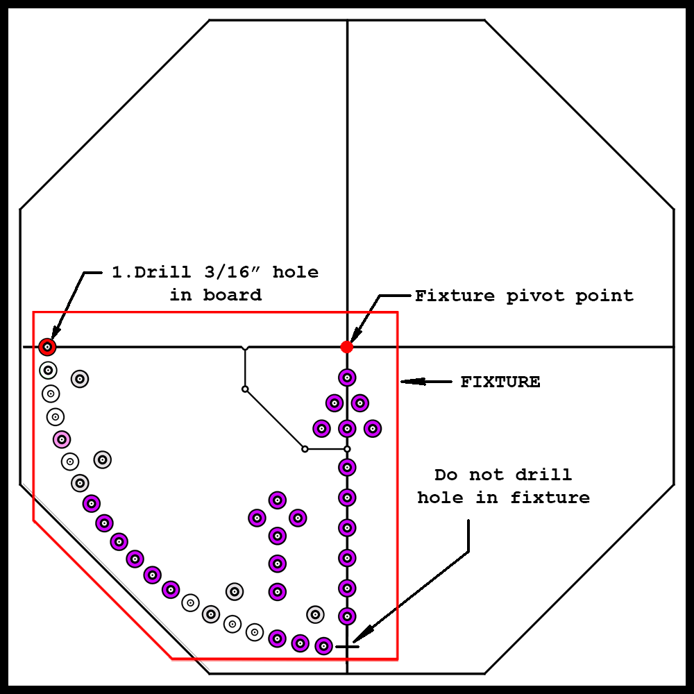

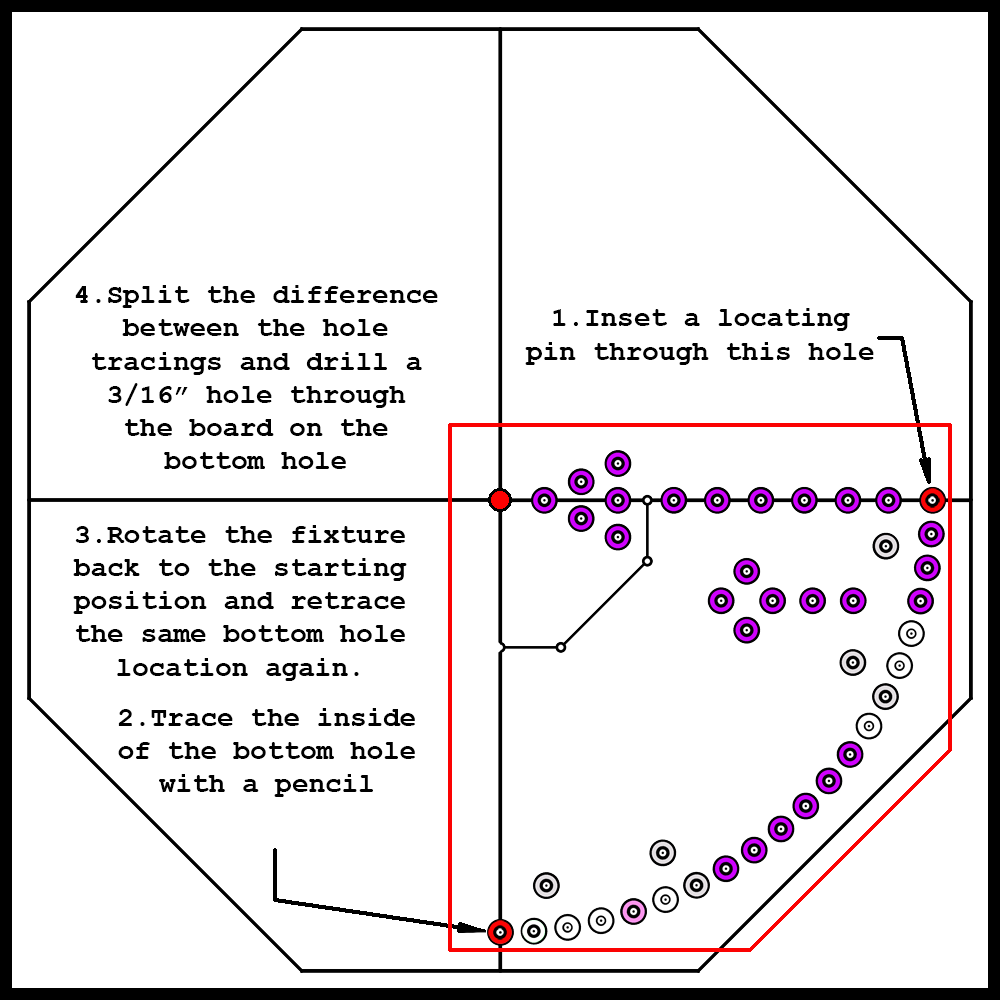
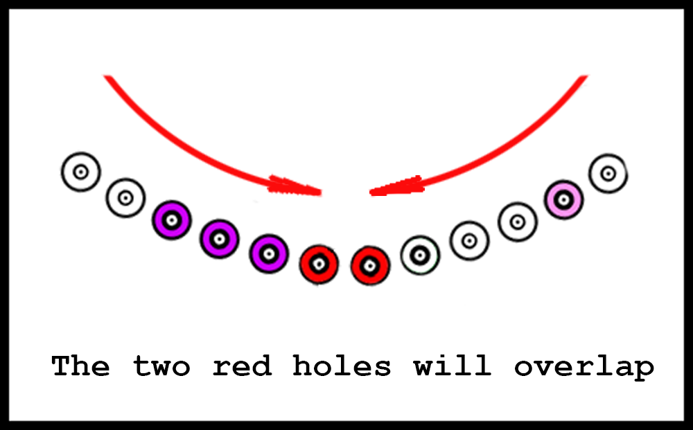
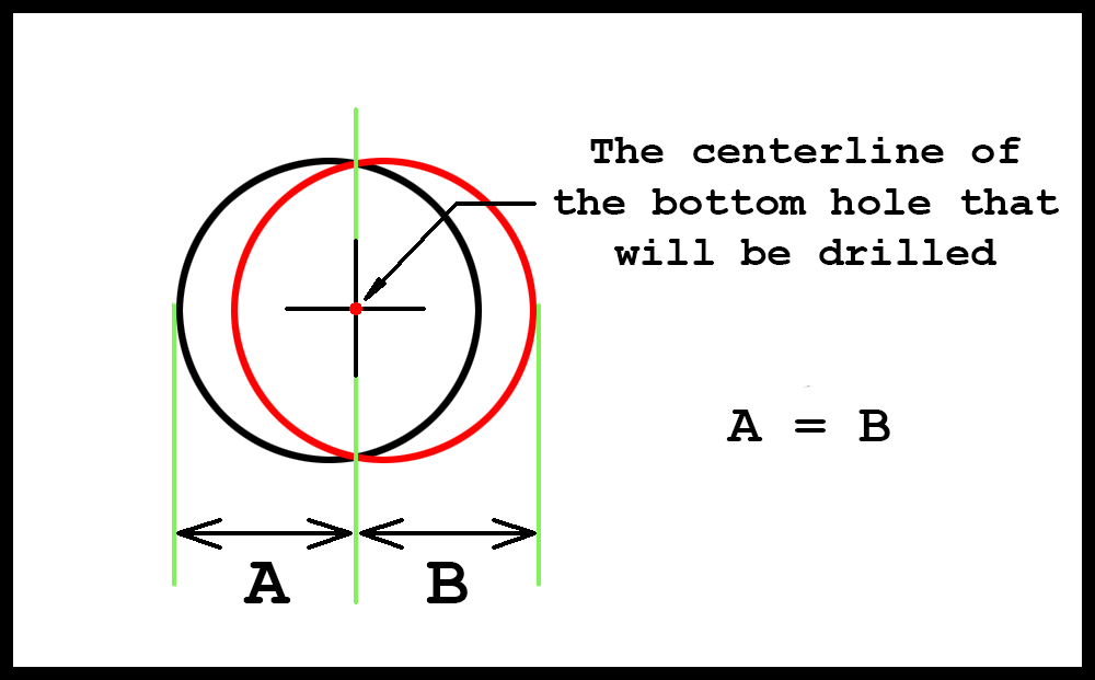
Step 5 above may be a little confusing. In this step the last hole that is at the bottom of the board will be drilled. Unless a CNC Milling machine was used, it is probable that, after rotating the fixture around the board, the final hole location will be slightly off center. That is why locating the hole visually over the Y axis in Step 2 is critical. If the hole centerline, for example, is 1/64″ on the left side of the Y line when the top hole is drilled, then that error will be continued the next two times the fixture is rotated. To minimize this error, locate the fixture as shown in Step 5, then trace the hole with a sharp pencil. Remove the locating pins and rotate the fixture 90 degrees clockwise back to the original starting position. Insert the locating pins and trace the bottom hole again. Move the fixture out of the way and look at the two hole tracings. They will probably overlap a small amount. If it is a tiny amount, then ignore it. Move the fixture back to the Step 1 or Step 5 position and drill the hole through the board. However, if the difference when examining the overlap is noticeable, draw a line exactly between the two hole tracings. Visually rotate the fixture until the hole is centered on this line. That is where the bottom hole will be drilled. The error will be cut in half equally.
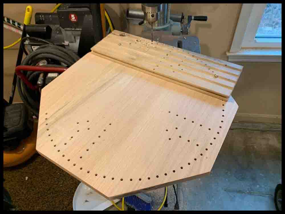
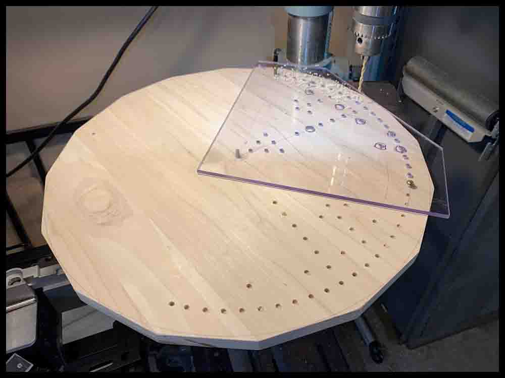
Once you are sure the fixture is accurate, you can start drilling holes. Transfer the holes in one section, then rotate to the next, using two #10 screws (anything 3/16 diameter) to locate the fixture in each quadrant. When transferring the holes, just drill most of the holes 1/8″ or so deep into the wood . (The four location holes shown in the drawings above will be drilled all the way through the wood previously.) Avoid getting wood chips and dust under the fixture as you drill. Be careful when lowering the drill into the fixture holes; you do not want the drill bit clipping the sides of the holes and tearing up the plastic fixture. After all the holes have been transferred, remove the plastic fixture and drill the holes all the way through the board.
Method 3: Use the same paper template that was used to make the poster board version.
To lay out the hole locations, follow the same initial steps that were used when making the poster board version in the first section. After transferring all the holes with a push pin, use a center punch to make a bigger mark where the pushpins entered the wood. To drill the holes and finish the board, use the instructions in Lay out and drill the holes – Step 5 in Method 1 for making a wooden base.
You will have to choose whether to make a raised SpacePort or just keep the whole board flat. If you make a separate SpacePort it will have to be reduced in size from the one made above that is six inches wide.
Method 4: Use a computer with a CAD program and machine the board on a CNC milling machine. Follow the blueprint on the right.
Final Thoughts
Pay the extra pennies and buy stainless steel screws. You will want your game to last and look sharp!
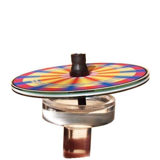
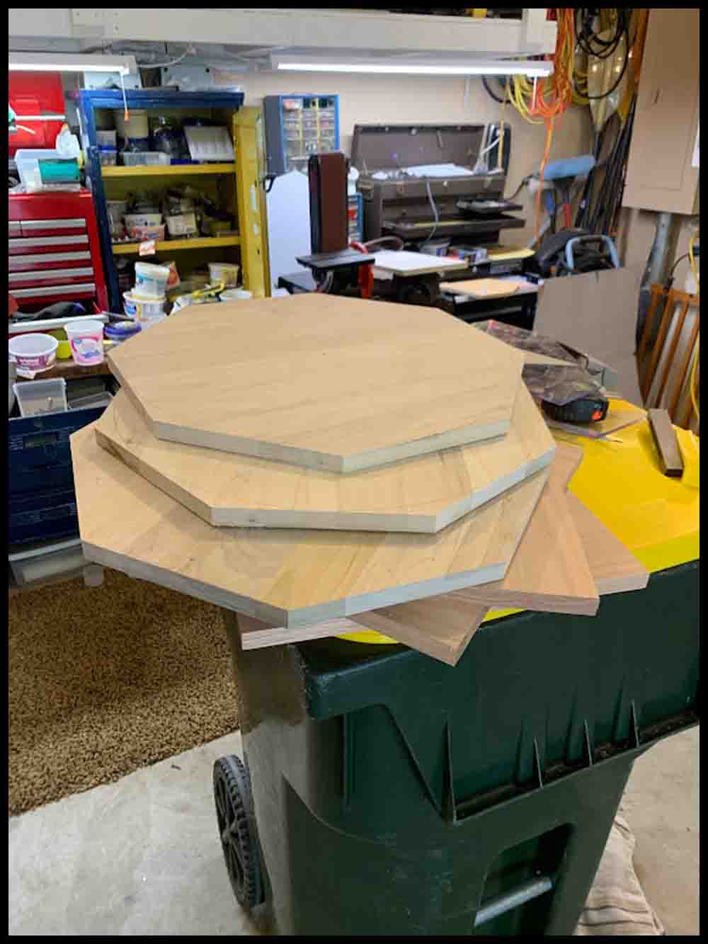
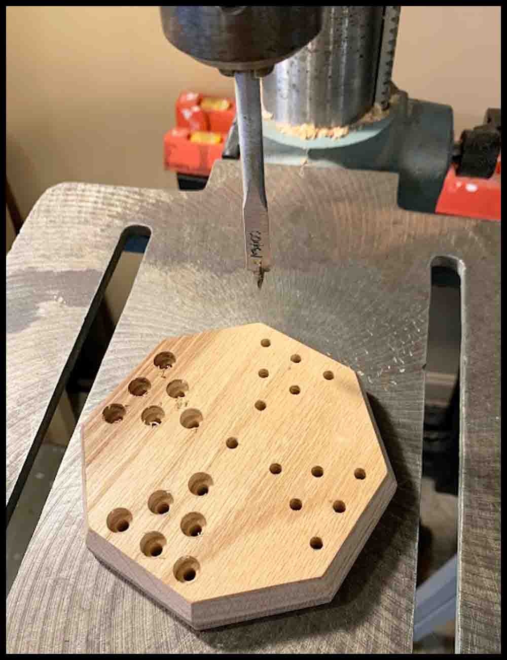
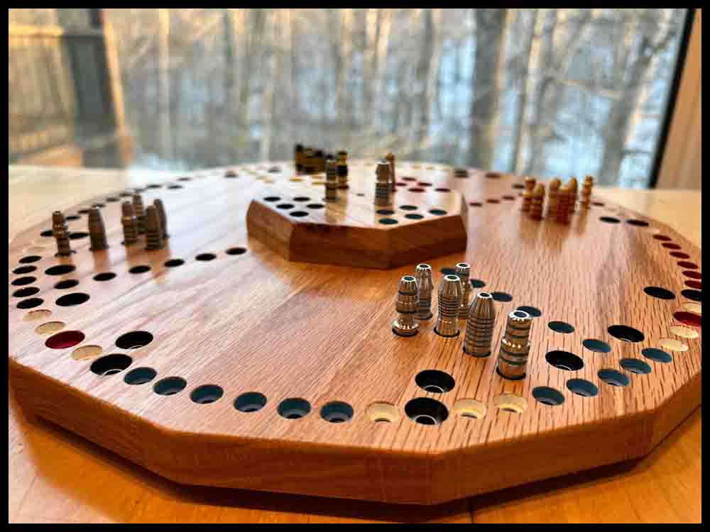
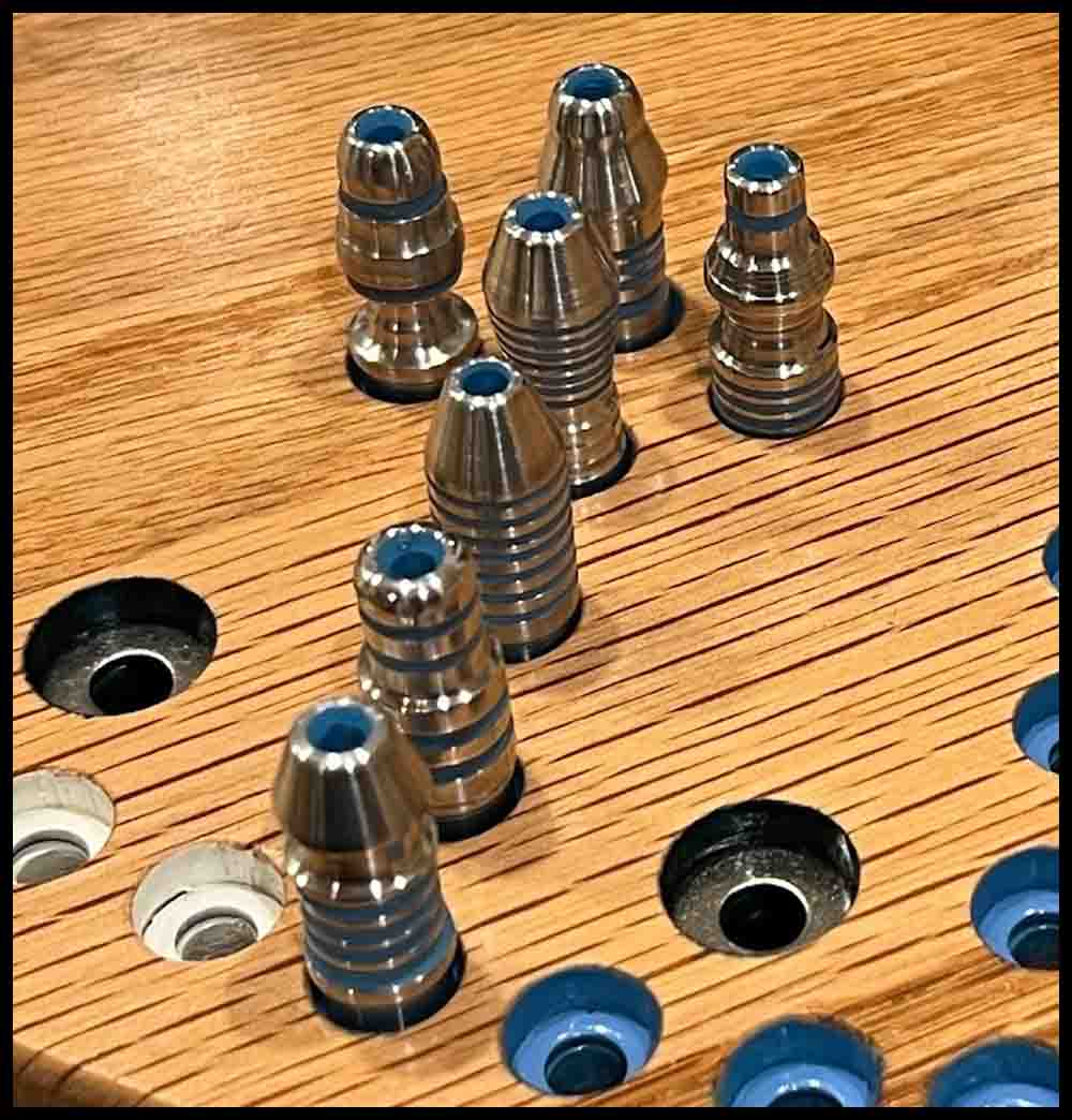
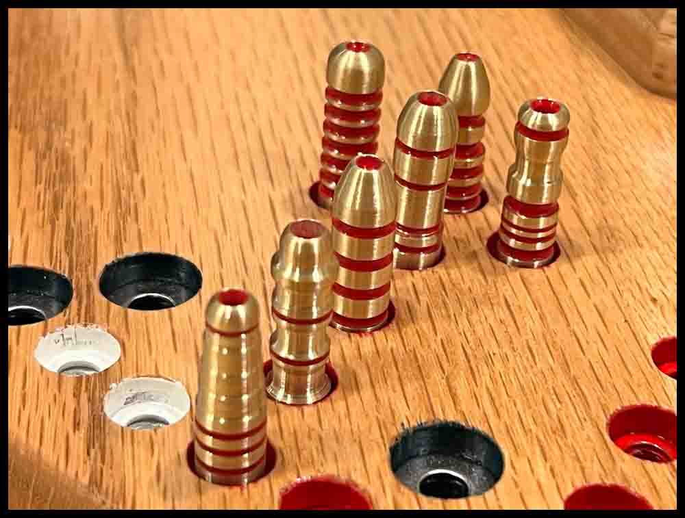
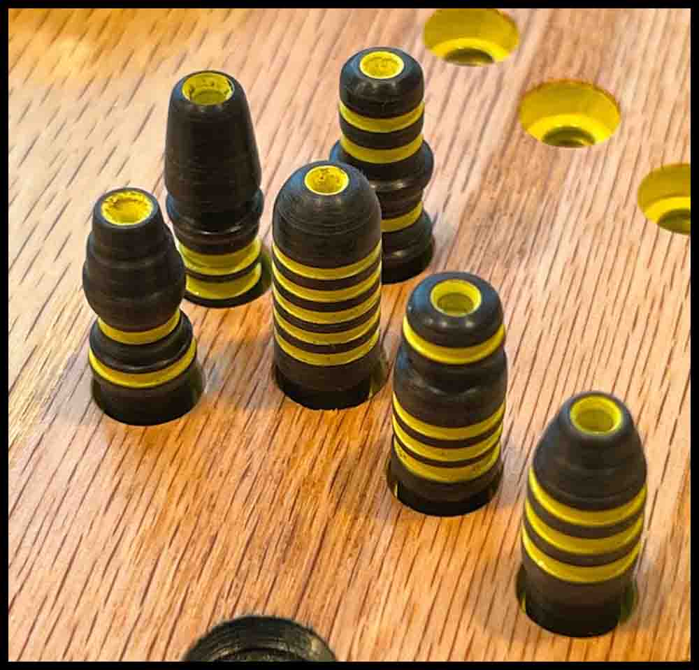
As I mentioned at the beginning of this page, I also have made a smaller wooden version of Octosory that uses rockets for game pieces. The width of this board is about 15″, with the main circle radius measuring 6 3/4″. The top of the holes are 3/8″ diameter with a 3/16″ hole through the board. This allows for Rockets with a diameter of 5/16″ to fit easily into the spaces. The hole through the board is the same as the bigger board, 3/16″. Of course, there was more work involved in making the Rockets instead of buying marbles. But I feel it was worth it. Every rocket is unique in its shape. Lathe work can be a blast!
The following pictures show details of the smaller board plus some Rockets I made in a lathe. The brass rockets shown below are red, the aluminum ones blue, and the stainless steel green.
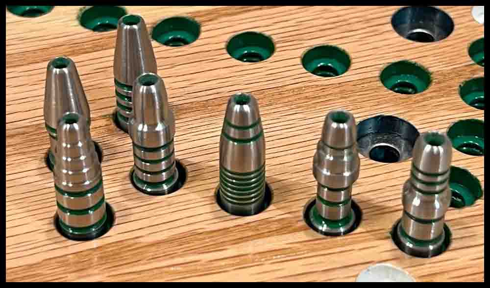
My first design before the WarpDrive was added in later designs.