GarsJunkpile is a collection of different things I have designed and fabricated over the years.
I started my hobby of inventing things back when I was a teenager. The first “invention” I recall making was a modified alarm clock. I delivered papers before and after school to pay for my high school tuition, and at times getting up at 4:30 in the morning was tough. I overslept at times, so I decided I needed a foolproof system to make sure I got out of bed. I borrowed my parent’s clock and set it to 4:30 am for everyday use, then took my own small electric clock and modified it to ring a loud electric bell at 5 am in case I overslept. To do this I first removed the clear plastic front cover and pulled out the clock mechanism. Next I poked a small hole through the clock face at the 5 o’clock position. After carefully rolling the exposed end of a wire tight, I pushed the bare end through the hole just far enough to touch the hour hand as it rotated around to the number 5. I was careful to not push the wire too far through the hole because I did not want it to touch the minute hand as it rotated past the 5 every hour. I hooked up another wire by wrapping it around the shaft of the metal hour hand and connected both wires to the bell and a big battery. When the hour hand contacted the bare wire the circuit was completed and the bell went off, fairly close to 5 am. To turn it off I would just bend the exposed wire down a little so it wouldn’t be touching the hour hand. I think this alarm system lasted maybe two or three days before my brother, who shared the bedroom with me, threatened my poor alarm clock’s life. 🙁
The other thing I remember making as a young teenager was very simple. I found a three or four foot length of rather heavy chain and bolted a trailer hitch ball to it. The result was a thick, very wicked whip, sort of like something a gladiator might use. Shortly after it was finished, my friend and I were walking through his subdivision when he started swinging it over his head, faster and faster, finally stepping forward and knocking a stop sign off a pole. His father found out and there was hell to pay!
When I turned eighteen my life changed dramatically. I had just started school at a local community college when I applied to become a Tool & Die Maker at a local factory. This involved a 4 year apprenticeship coupled with more college courses. The first year was supposed to be spent in the “training room” where we learned to operate different machines such as lathes, mills, and surface grinders, as well as learning to weld. A couple of months before my year was up I was transferred to a special drafting assignment in the engineering department to help engineers set up a small air-conditioner plant in Tennessee. I thought it was pretty cool to be a teenager wearing a shirt and tie while drawing on a big drafting board like my Grandfather had done. (He was a Civil Engineer). I soon realized, however, that while I enjoyed drafting work and the opportunity to design fixtures and related tooling, I also missed running the new equipment I had been training on in the Apprentice Training Room. After six months in drafting, I was moved to the first of six different Toolrooms. I found that I really didn’t mind getting my hands dirty. And at times they got very dirty!!
The red arrow on the right will return you to the top at anytime.
A fun photography project I added to our family room a few years ago.
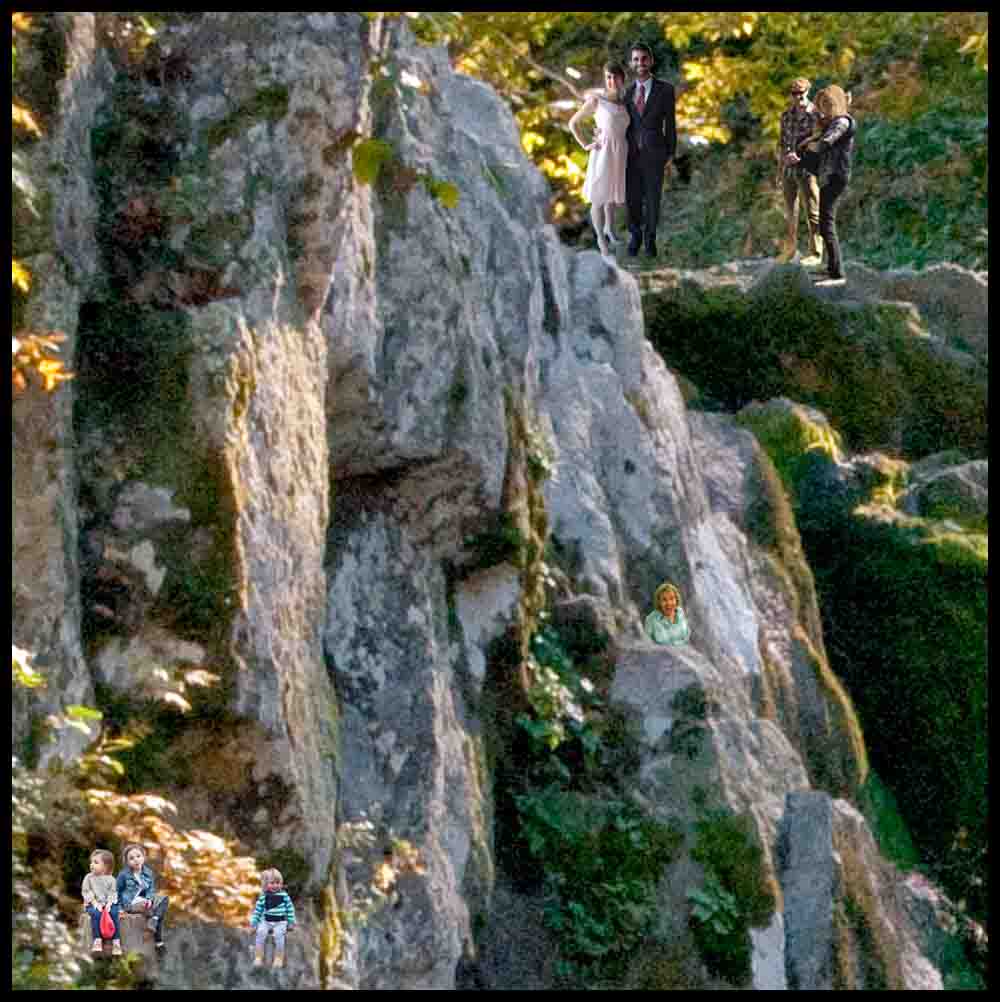
In the following series of pictures a project that I had lots of fun with is shown. Like most people, we have tons of vacation photos. One day I decided to do something interesting with them. I picked out a bunch of photos that I liked and opened them in Photoshop, sizing them to 16″ x 20″ so I could make them into canvas prints. I built a wall frame that would hold eight prints and mounted it on the family room wall. The pictures just pop into place, held by strips of foam, and one day when I make some more I can interchange them to change the look.
What makes them unique is what is semi-hidden in them. I took over 20 pictures of my kids and other family members, including pets and a few other objects, and shrunk them way down. I had to really crank up the resolution so they wouldn’t just be a pixelated blob. The fun part was inserting them into various positions in each picture. If I didn’t like where they were I would just take my mouse and move them to a new location. If you move the sofa out of the way and get real close with a flashlight you can see them all. It is even more fun now, years later, because I forgot what and were I placed some of them! One day I may put together a little book showing where everything is located.

In the first picture below, Epcot at Walt Disney World is shown, followed by two closeups of the same picture. My Mother is pointing to one of the images of her in Epcot in the fourth picture. She thought it was hilarious! (She has never been to Walt Disney World). I also have her looking out a window of an old house on Mackinac Island (where she has been), submerged almost to her neck in a creek in the Smoky Mountains, and sitting on a rocky beach on Grand Cayman Island in the Caribbean. Click on the pictures of Epcot below and you can see a few of the images I added.


The next picture is one my friend Brent took when we were hiking in the Smokies near Caves Cove. Brent is a very good photographer and had his own darkroom when he was younger. He’s a hell of a bowler, too! What is kind of cool here is that while he was taking the picture, I took a picture of him taking the picture! I inserted him on the right side of Abrams Falls, next to one of my sons and his wife.


The first of the final two pictures I am showing here I took on a Cruise that started in San Juan, Puerto Rico. The picture is of the huge fort on the edge of the island, San Felipe del Morro Castle. The last two pictures are on a trail in the Smokies. This was one of the most fun and satisfying projects I have ever undertaken!


Pictures from my days as a Tool and Die Maker
The first section below will display pictures and narration that hopefully will show a little of what a toolroom looks like and some of the tools universally used by machinists and tool & die makers.
So some readers are maybe asking, what is the difference between a machinist and a toolmaker? Well, (and this is maybe over-simplifying things a bit), a machinist runs machinery like milling machines, lathes, drill presses and grinders, often working from a blueprint, and a tool & die maker specializes in making and repairing dies, molds, jigs, and fixtures as well as production machinery using a machinist’s skills. That being said, the fields overlap in places and the differences can be quite murky.
Almost all of the pictures may be enlarged by clicking on them.
Toolroom and Factory Pictures


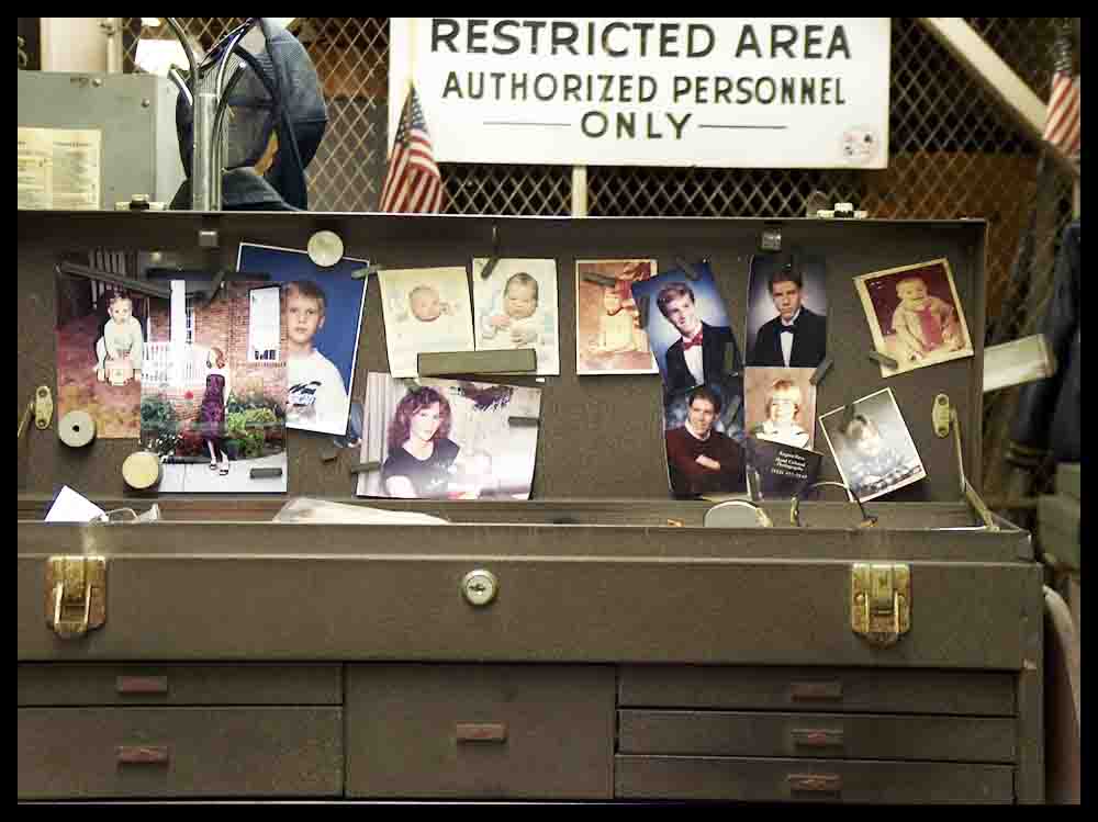
Photos of an automatic die
Most dies we worked on were made outside of the production factory in smaller job shops. With this particular die, though, I was fortunate to both design and build it myself from scratch. We didn’t have any Wire EDM machines yet when this was built, so when making some of the die sections I used fairly new CNC milling technology for the cutting geometry.


Toolmaker Tools
Every toolmaker will acquire certain tools during his or her career. Some are purchased or given to them by older toolmakers, but most are made by the apprentice or young toolmaker themselves. I have lost or given away some of my tools since retirement, but kept the ones I have displayed here.

These are some of the remaining tools I made and used as a Tool & Die maker.
In the pictures below I will briefly describe the tool and what it is used for.


This is how you use the edge finder on the left: The black circles are the tops of dowel pins that tap into the hardened steel plate. The relationship between all 5 holes is very precise. The pins will butt up to the sides of your work, and the precision ground hole between them can be located on the milling machine, jig grinder or other machine using a dial indicator. It is centered exactly over the intersection of the two sides. You can see the corner of the work through the hole. The extra hole at the top left is for another dowel pin when needed.


My pair of angle plates, now almost 50 years old, are now serving as bookends and doing the job well. 🙂
The thick book on the left is the Machinery’s Handbook, which is often referred to as the Machinist’s Bible. We all bought one our first day as apprentices. The two books on the left were written by friends of mine. One of the authors, Jerry Arnold, tried to talk me into being his die designing apprentice when I was his 15 year old paper boy. I was too stupid to say yes. I mean, what the heck is a die?? Oh, well. How ironic that three years later I would become a Tool & Die apprentice and eventually, years later, work with Jerry on some equipment as a Journeyman. The second author, Jim Geary, was a boss of mine in the toolroom at one time. He was a very smart and friendly guy!

DRUG TEST?? Boss, you can’t be serious!!
There’s a story behind that picture. 🙂
If you find this little narration about Tool & Die interesting, there are a few paragraphs entitled “A Little History on CAD/CAM Development” written at the beginning of the page “Make a Game: Rainbow Raceway” that may be worth reading.
Putting Toolmaker skills to work!
On display from this point on in this rather lengthy web page are a few more of the the objects I’ve made over the years. Some of them are stuck in boxes and drawers but others are still used in every day life. Even further down the page are several home projects I finished. There are quite a few pictures on this page! . You make click the red arrow on the right at anytime to return to the top.
Click on any picture to see a larger version in a separate tab.
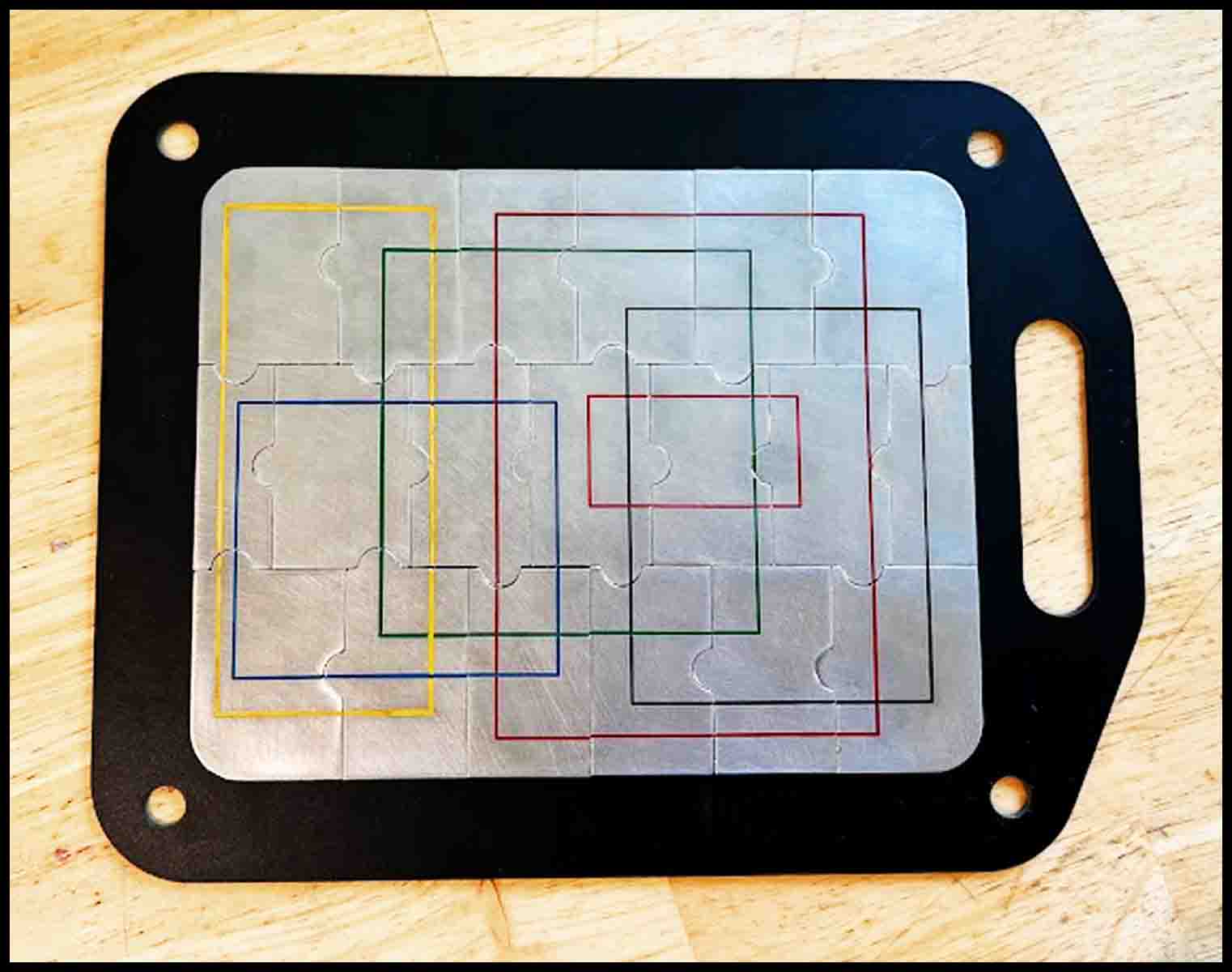
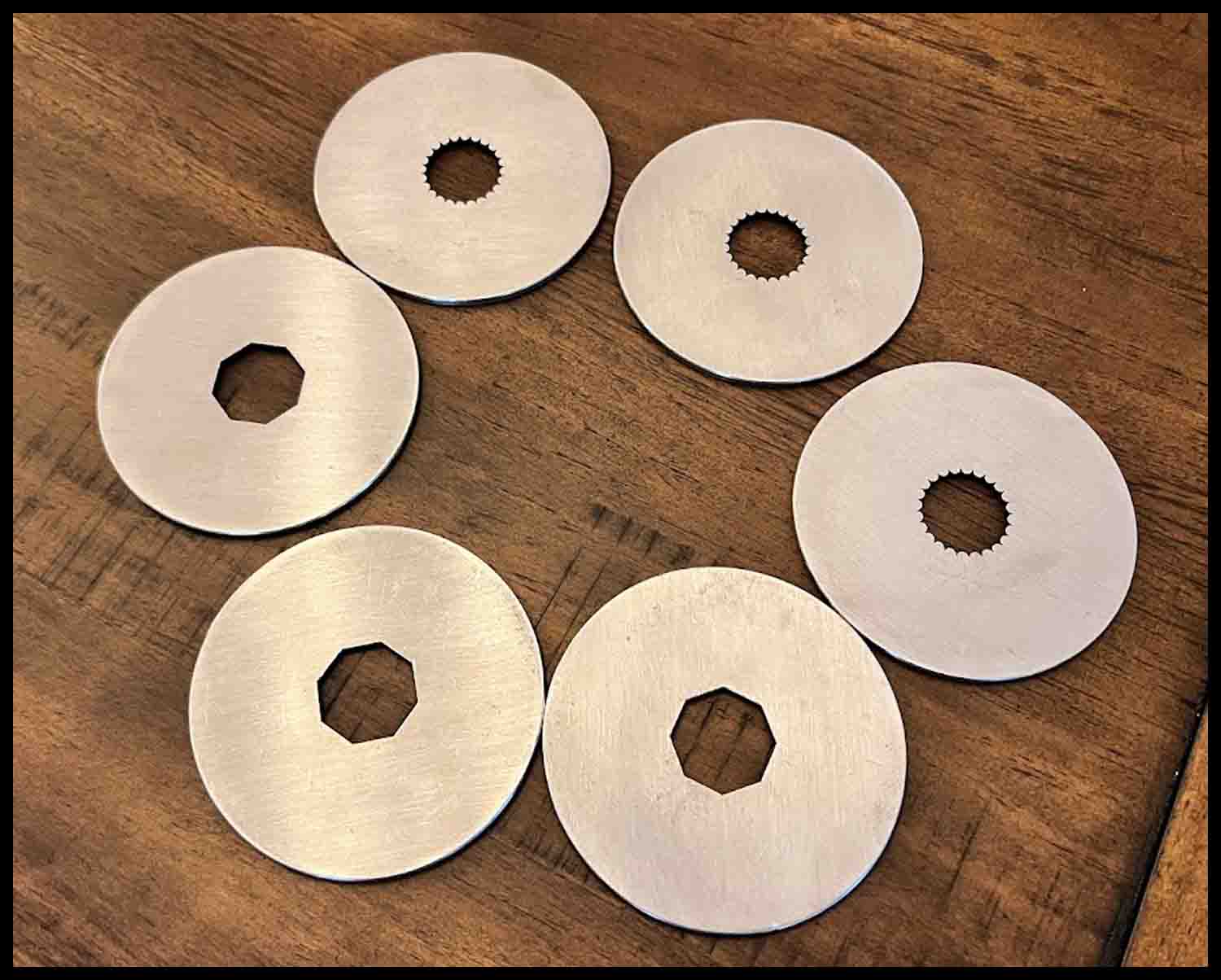
Stainless steel jigsaw puzzle
I made two of these puzzles for my youngest kids when they were small. They are two sided. One side displays their name, but the other side is different for each. One has rectangles cut into the surface while the other puzzle has intersecting circles displayed.


Stainless steel circle puzzle
These circle puzzles are fun to put together, but can be difficult if both sides look the same. I took one of my puzzles and scratched up one side with sandpaper so you could tell the top from the bottom, making it easier to assemble. Another puzzle has more pieces, thus making it more difficult to put together.


Block Truck
This project took a LONG time to do. The truck was made back in the late 80s after my youngest son was born. It was a Christmas present for him. I used some discarded scrap rock maple and worked through my lunch breaks and evenings at home. Each block had to be hand sanded and painted. The hubcaps and headlights are made out of stainless. The two blocks in the middle picture were left over; one of them was used for practice. This truck is also the cover picture for my game LetterLimo.
Over the years this truck has been played with by several of my kids and now the grandkids. Nobody’s broken it yet!


Having fun with Aluminum
In the first two pictures my aluminum nutcracker is displayed. The two on the right show a simple roller toy.


Stainless steel tennis racket jewelry


The tennis racket shown on the left was made sometime in 1989 as a graduation gift for my oldest son. I engraved it on one side and bought a sterling silver necklace to hang it from. It was quite complicated to make. After designing the shape on a computer, I had to figure out how to make the strings. I came across a small piece of stainless screen mesh, then sandwiched it between two steel plates. I was then able to cut it out with a Wire-EDM machine, making it about .010″ bigger overall than the opening in the tennis racket (which was also cut with a Wire-EDM machine). Next I had to grind a very small t-slot milling cutter to the thickness of the screen (plus a couple of thousandths) and use it to machine a tiny groove in the middle of the opening. I achieved this by first setting the depth of the cutter to the exact middle of the tennis racket that was laying flat on the milling machine table. Then I was able to carefully slide the racket around by hand with the cutter, which was spinning somewhere around 1000 rpm, slowly eating away at the interior opening. I had to remove just enough metal, by trial and error, to allow the screen to snap into the racket using just a little pressure. Stainless is tough to machine, and a slight wrong move would have caused the cutter to grab the steel, ripping it away from my fingers. I have to admit this was very nerve-racking!
Pizza Cutter
One of the most utilized gadgets I’ve ever made is this pizza cutter. It’s probably sliced several hundred pizzas over the years. Depending on what works best for the user, it can be flipped over to deliver more force for those tough crusts.


Stainless steel hydraulic black powder muzzle loader
While serving my Tool and Die apprenticeship we were encouraged to make things from blueprints. The skills we learned were later applied in our Toolmaker jobs. I am not a gun collector, but I sure enjoy making things! I wish I had a picture of a cannon I made for a friend back in the 70s; we test fired it in a field and the shock waves nearly blew the windows out in the houses surrounding us!
The four muzzle loaders shown on this page are not capable of being fired anymore. I just had fun making them!
This rather unusual looking black powder muzzle loader was conceived, designed, and built by me when I was a young guy many years ago. It has never been fired; I valued my fingers more than I wanted to make it fire!


There are two hydraulic cylinders, one on each side of the barrel, that are connected with copper tubes to a smaller cylinder underneath. When either thumb presses the cylinder button forward it forces fluid into the bottom cylinder, which releases the striker, thus detonating the percussion cap on the nipple next to the handle.
Martial Arts Weapons
Back in the 70’s I was into karate for a while. I gave my best pair of Nunchakus to a friend in our group many years ago. Wish I remembered who got them!


Horseshoe Checkers

The items on the left are Horseshoe Checkers I designed and built. I used to throw horseshoes with my friends and we would play all summer long in each other’s back yards. I even had lights set up for night games. We probably drove the neighbors crazy!
A thrown horseshoe, unless you’re playing barnyard rules, has to be within a horseshoe length of the pole to be legal. These checkers will butt up against a pole with a diameter between 3/4″ and 1″ and then give an accurate measurement showing if the shoe is legal or not. It will also resolve disputes over whose shoe was closest to the pole.

Stainless Steel Items


More Odds and Ends


The pictures on the right are of a 1967 Datsun Pickup a friend gave me. I took the rusted bed off and welded up an angle iron frame, then added a wooden bed on top of the frame. I rebuilt the engine and had the head welded up twice; twice I jig-ground the weld away from the valve seats. Both times it leaked and I had to buy a new one. The Japanese carburetor was bad and I couldn’t rebuild it, so I made a special aluminum manifold and mounted a Chevy two-barrel on it with a manual choke. The finishing touches were some K-Mart gauges under the dash and 2 toggle switches for turn indicators. I will have to say it turned some heads when I drove it down the street! Eventually my sister wrecked the door and I gave the truck to my brother-in-law.


Jewelry Maker’s Ring Mandrels
These three pictures show a ring mandrel I made for a kayaking friend a long time ago who was a jewelry maker. The rods screw together (I don’t remember exactly why) :-), but anyway they are used to size rings. Each step in the shafts correspond to different ring sizes.


Stainless steel belt buckles, keychains, and game pieces

In the top right of the picture on the left is part of a present I made for my brother and his wife. In real life it hangs on a tennis net that is in between them (not shown). They met playing tennis. Maybe he’ll send me a picture!
Below that piece are various ornaments and keychains I made for different people.


Tower Puzzle
This Tower Puzzle takes a lot of dexterity and patience to maneuver a steel ball from the top downwards, layer by layer. In the second layer there are two ramps side-by-side. After making it to the top of the first two ramps, the ball goes sideways through a plastic tube to a third ramp. At the top of the third ramp is a hole that allows the ball to drop down to the next level. To move the ball up the ramp can be very frustrating, but it is quite possible. A house guest did it recently with only 5 minutes or so of practice. Good job Linda!
One feature shown in the photos is the ability to change layers when desired. Just remove a few screws, carefully take off a few side panels, and change the layers however you want them! Make it easy or difficult. The small vertical pipe in the picture on the left is a return tube to transport the balls back up to the top after they reach the bottom.


Of course not everything I have made is displayed; I regret that I have little or no pictures of some earlier projects. One project in particular I was fond of was a power tilt and trim system I designed from spare parts for a 16 foot runabout. The 85 hp Mercury outboard motor was very hard to tilt up by hand, and the trim could only be adjusted by moving a pin to different hole locations. I designed a control panel that was connected to a hydraulic system consisting of a 12 volt pump powered by a car battery, two cylinders, a control panel, and an oil storage tank. An on/off switch would tilt the motor all the way up or a button could be pushed that adjusted the trim in very small increments. The system was very heavy but worked well.
This is the only picture I have of the tilt and trim. The red arrow points to one of two hydraulic cylinders mounted on the back. They were each connected to stainless bars that went backwards from the end of the cylinder rod almost to the transom where they were joined to each other behind the motor. When the rods extended they would tilt the motor upward – in theory. The first time I took it out on the river to test the system it was almost a disaster. Both sides of the assembly bowed out sideways, bending the cylinder mounts. I had to quickly shut it down and pull the boat out of the water. I ended up adding a solid bar behind the motor that tied each side together. This assured that the cylinders would work together as one unit. Problem solved!
I had a cutoff switch designed into the control panel that would cut the pump off when the tilt reached a certain level from pushing the button. Another switch would tilt the motor all the way up. I found that when in the water I could bypass the safety cutoff and jog the motor up until the propeller was just underneath the water. It would shoot a rooster tail up in the air like a Hydroplane racer in the Madison Regatta! Of course the boat was only going around 5 mph. I am so lucky I didn’t blow up the motor. The RPMs were redlining on the tachometer!
