
A Little History on CAD/CAM Development
Not a history buff or just not interested? Skip ahead to start making your own Rainbow Raceway game.
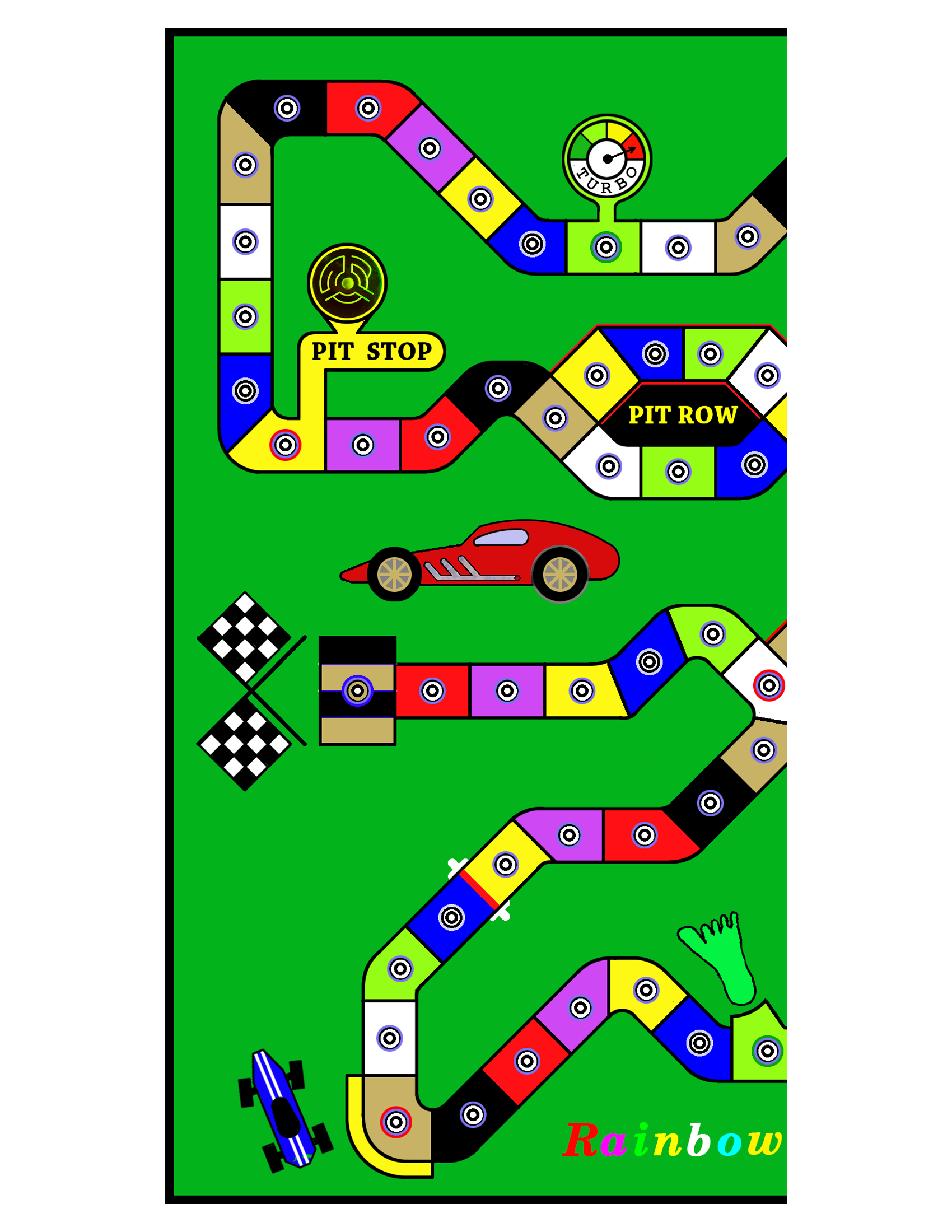
The pink game shown above was one of two I made over thirty years ago for our two youngest children. That is the original design. They were designed on an early CAD/CAM system made in a software program called Esprit. That company is still a leading cad/cam developer today. CAD stands for Computer Aided Design; CAM is an abbreviation for Computer Aided Manufacturing. This year I updated the game by redrawing the racetrack path in Photo Shop and adding several new features: Pit Row and the Emergency Runaway are hazards, while the new Tachometer is like the original Turbo. Racers who land there get an extra turn. Click, then zoom with the + button on the the picture below to see the new features up close.

To make a part using CAD/CAM, first the toolmaker would draw the geometry on the computer, then, using another component of the software, they would use that software to establish where the tooling path was going to be. This was called adding a structure to the drawing. Finally they would input specific information that would allow the computer to write machine code for the individual machine being used, such as a CNC Milling Machine, Wire EDM, or Laser Cutter.

For example, suppose a toolmaker wanted to add some socket head cap screw mounting holes to a rectangular piece of tool steel they were making for a stamping die. We will call that piece of steel a section. Usually conventional machines and methods would be used to make the rectangular section, such as a saw, milling machine, and surface grinder. After the section was squared up and finished to its final size and surface quality, the section would be secured in a precision vice mounted on the CNC Mill. Moving to the computer, the toolmaker would draw the part using the Esprit software, then add a structure onto the part, showing where the holes were located and how deep to drill the holes and counterbores. Finally a tool path would be generated after entering specific information such as tool diameter, total depth of cut, incremental depth of cut, and feed rates. The finished program would then be transferred via wire or tape to the CNC Milling Machine. The toolmaker would orientate the machine in relationship to the section by using certain tools that would establish a (0,0) starting point on the front left corner of the part. (Tools I made to find corner locations are shown in a section of GARs Attic). Next the machine table and spindle would be moved by the toolmaker in manual mode to establish the relationship between the top of the workpiece and the bottom of the cutting tool. This is referred to as TLO, or Tool Length Offset. After turning the spindle on and hitting the start program, the machine would take over. A funny thing we all learned early on was that the machine would go exactly where you told it to. 🙂 So what if a ten inch chunk of steel was in the cutter’s path? The machine doesn’t care! When in doubt, a toolmaker might lower the table a few inches to perform a dry run before actually cutting on the steel.
In the early days of our toolrooms, most metal working machines were all manually cranked to different positions when machining. Indexed dials were built onto the handles so accuracy could be maintained. One revolution of a crank might move the machine .100″ of an inch, so cranking the handle ten times resulted in a one inch move. Then one day a vendor brought in a LED Digital readout and installed it on a small milling machine. This readout would display the machine’s location in an X ,Y plane in thousandths of an inch; some were even capable of displaying locations in ten-thousandths of an inch (1/10,000″). For toolmakers, the introduction of digital readouts was like experiencing air conditioning for the first time! Different problems that affected machining, such as leadscrew backlash and tool chatter, could be controlled with more precision. Moving the machine to a specific location was immensely easier. (Did I turn the handle 32 times or 33??). You get the picture!
The next step in increasing the efficiency and sophistication of machine tools was the development of Machine Code (or Machine Language, as it was sometimes referred to). Before the Esprit or other software systems (described in the first paragraphs above) were invented, toolmakers had to personally figure out the coordinates on a tool path that described each line segment and arc, as well as the vertical distance the machine would travel when performing each task. Figures like G1, G3, and G85 all meant something to the machine. Using a blueprint as a guide, a toolmaker typically would write the program out on paper, verify the accuracy of their figures, then type the machine language into a special typewriter that would punch out a long tape with holes in it. The milling machine had an optical reader that would read the tape and perform the machining. We were thrilled with that ability! Some of the first computer nerds (who played with Commodore 64 computers at home) became the gurus of the toolroom. I learned the systems from these older guys. Soon organized classes were held, with company representatives from the software companies teaching us, sometimes in their offices or newly built classrooms in our shop.
The best classroom, however, proved to be the Milling machine itself. Book learning was still being developed. Some of the engineers who wrote the study materials may not have had much experience with actual toolroom conditions. Over time, some toolmakers developed certain techniques that made the machining process smoother and more accurate. (For example, while cutting a tough material, you might “fool” the machine into thinking it was using a .750″ diameter cutter that was actually .740″ diameter. This was a shortcut to producing an accurate finish on the material without changing tool offset as often). Other techniques we developed for certain machining processes might involve developing sub-routines that switched from Cartesian coordinates to Polar coordinates, then back again.
Most of our toolroom bosses realized the need to learn on the machine. Sometimes the right jobs were not available or needed at a particular time that might serve as a teaching experience for some of the new machines. Technical skills needed to be developed to increase the speed and cost efficiency of using new CNC equipment. That period of time in the Toolroom, the mid to late 80s, coincided with my new found hobby of making board games. If a toolmaker who was interested in developing their skills was not on a “hot” job or project, or maybe on a lunch break or after our shift was over, we were allowed to perform “government work” on our own. I know with certainty that the skills and techniques I developed during the course of making games and other “government work” became very useful when making a die section or fixture for the company. The foremen and managers knew where to go when an intricate job was required to be completed quickly.
Material was not hard to come by; I have picked different items out of trash gondolas many times that had been discarded. They were destined for the garbage heap or scrap yard. Also, if a special plastic or metal was needed for a government job, there were local outlets that the material could be purchased from by an individual. Sometimes we were allowed to use unused material to make things and then purchase the material from the scrap yard, usually paying by the pound. Back in those days there was LOTS of waste in the factories. And, as mentioned earlier, there was a payoff to the company in terms of skills acquired.
This all leads to how I made my games using certain methods developed along the way. The pink game I called “Angela’s Motor Raceway” that I made for my daughter was constructed with two pieces of plexiglass. The top was 1/8″ thick, the bottom approximately 1/4″ thick. The top was mounted onto a special fixture that allowed for taking the game board off and on the machine table multiple times. By doweling the fixture directly to the table (shop owners cringe) I was able to return the board to the same relative X0, Y0 location every time. After drawing the design with the Esprit software, I added G Code to mirror the image. Using a #1 center drill as the cutter, I made several passes up to .010″ deep when cutting the design. Liquid soap in a spray bottle mixed with water provided coolant. (Of course, after each session the machine would have to be dried and occasionally coated with oil to prevent rusting. I took good care of my baby.)
After the image was cut in the plastic and the mounting holes drilled, the top and bottom were screwed together and the holes for the game pieces were drilled (without mirror image activated). The drill went through the top and partway into the bottom. The sides were then given a skim cut with a milling cutter to arrive at the final dimensions. Ready for painting!
Painting was actually very easy. I used oil-based model paint with a small tipped brush and just filled in the grooves. Excess paint was slopped over the edges of the grooves; it didn’t matter. Once the paint dried, the whole “bottom” of the top piece was sanded with fine sandpaper. After applying several coats of pink spray paint, the top was finished. Some wording was cut into the top of the bottom piece and painted the same way, followed by more sanding and pink spray paint. The halves were screwed together for the final time, custom made legs were added, and the gameboard was finished!
The first picture below shows an example of how the engravings were painted. It is another game started years ago and never finished. Gold paint has been applied, but was not sanded. The two halves are screwed together for storage. If you look closely, by clicking the image and zooming in, you will notice the longer engraving in the lower half of the picture is in the correct orientation while the two small places above it appear backwards, or displayed in mirror image. That is because the picture was taken looking at the bottom of the game. The two smaller engravings (which are initials) will appear correctly when the board is turned right side up.
Using the same Esprit program, the stainless game pieces were designed on the computer, then cut in a Wire EDM machine. The bottoms of the game pieces needed to be round where they enter the game board, so a special fixture had to be made to turn them in a lathe. The Red Cards were milled out on the CNC Milling machine using sign material I bought locally. Eight-sided dice of various types completed the project.


The history lesson is over! I will show a person how to make a nice gameboard using simple techniques below. The first project uses foam poster board to make the game. The second project will show how to make a nicer game out of wood. Even further down the page you will find a picture display showing a smaller wooden board coupled with an image printed out on a standard 8 1/2″ x 11″ piece of photo paper.
12″ square Rainbow Raceway Game built with a Wood or Foam Base
Remember to click on any picture to see it enlarged. Click the square in the video controls to see the video full screen.
Regardless of whether you make a foam or wooden base, choose your design from the four samples below, then start with steps A thru D first:
Click on the pair of images to print out two halves. High quality photo paper produces an attractive game board surface, but card stock will also work.


Cut and assemble the Rainbow Raceway image.
A. Cut Left Side A exactly at the right side of the image, being careful to not have any white showing along the edge.
B. Attach a small piece of transparent tape to the very top and bottom of Side B to secure the paper directly to the table you are working on. This will make it easier to attach the rest of the tape.
C. Place Side A on top of Side B and slide it around gently to match up both sides exactly. Now tape down Side A just as you did before at the top and bottom.
D. If no further adjustments are necessary, take a long strip of tape and carefully lay it across the middle of the joined edges. Be Careful! Once the tape touches, it doesn’t want to let go. It doesn’t hurt to practice beforehand with some scrap paper to develop a technique that works for you. After taping the front down the middle, remove the small pieces of tape from both sides that held the papers down. Lift the joined sections from the table, flip the pieces over, and tape the other seam on the bottom. Finally, trim the taped images to the black border with scissors.


Foam poster board for the base.
There are many different materials that can be used as a base for the Rainbow Raceway game. The following directions show how to take the image assembled above and apply it to foam poster board. This will be the easiest and fastest way to make a nice, attractive game. Further down the page I will show how to use a thin piece of plywood as the base. Any type of wood or other material may be substituted.
1. Cut the poster board using a razor knife and straightedge to a size about 11 1/2 ” to 12″ square.
2. Lay the taped image on the board where you want it positioned. Make a few light pencil marks on the square poster board to use as a guide when maneuvering the glue laden image into position.
3. Glue the game image to the poster board as described in the next paragraph. I used kid’s school glue on my first board but was not happy with the results. After doing some research, I bought a couple of bottles of Aleene’s Tacky Glue. It dries clear and is water soluble and works fairly well. However, there are plenty of choices for glue available.
To help apply the glue with a minimum amount of mess, use a couple of small pieces of clear tape to secure the image face down on a large piece of scrap poster board or smooth cardboard. Squirt a rambling pathway of glue all over the image, then spread the glue evenly around the surface with a flat foam brush or a small piece of scrap poster board. Carefully remove the image after applying the glue and center it on the poster board, lining it up with the small pencil marks. Place a dry sheet of paper towel on the image and use your hand to apply pressure and gently smooth the surface flat, working out from the center. Wipe any extra glue away with a damp paper towel. Try to not get any glue on the top of the image.
4. After the glue has set up and dried, one option that will prolong the life of the board is to use some clear wrapping tape to seal the image to the poster board, centering the tape along the edge of the image. Apply the tape carefully, covering both the image and the poster board on all four sides. Note: If you want to change the color of the white border showing around the image, do so before taping.

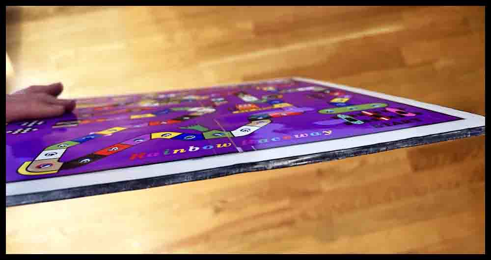
Note: The camera angle makes the board look rectangular. It is square. Also, the image is not trimmed to the black borders in this picture.

Continue with Step 5 after reviewing A-D below.
The following few paragraphs show some tools for piercing holes in foam board.
Click the pictures for a bigger view.
A. The first tool in the top picture is a push pin. It works great for piercing the initial holes through templates made out of cardstock used for making Octosory and Aggarv8ion. For Rainbow Raceway and Orbital Summation, push pins are used for the initial mark in the image of the game that was printed out.
B. The metal scribe shown below the pushpin is a great choice to use as a center punch on wooden bases that have been pre-marked with a push pin. The enlarged view of the tip is just to show this particular tool. The important part is the nice sharp point.
C. The third tool from the top is a homemade scribe I have used for years. This is the perfect size (1/8″ diameter) for opening up the small holes initially made in all of the foam boards. The sharp point assures the hole location is picked up accurately. Search for a similar pointed awl or scribe in a hardware store or use a screwdriver like the small one described below in D.
D. The Phillips screwdrivers offer three different sizes for piercing clearance holes. The small one (.120 dia.) can be used the same way as the homemade scribe above. The point is small enough to pick up the initial small holes made in the poster board, although it might be helpful to grind more of a point on it with a belt sander.
E. Two games will use a slightly smaller diameter piercing tool. Orbital Summation and the smaller version of Rainbow Raceway use #6-32 screws to make the game pieces. The tools shown in the lower picture were both made from drill bits found around the garage. The shorter drill uses a wire nut for a handle. On the longer carbide drill I found a plastic drywall insert to use as a handle. Both handles are taped on with duct tape.


5. Use a pushpin or steel scribe to make a tiny mark in the exact center of each circle in all of the spaces. These holes will be opened up in the next step, so just concentrate on accuracy.
6. Using a pointed tool approximately 1/8″ diameter, pierce a hole all the way through the top image and the foam board. A slight bit of side pressure with a twisting motion can be used to keep the hole centered in the process.


Note: It is possible to enlarge the holes to their final size in one step, using just one tool. However, I feel a person will have more control over accuracy and neatness by using several steps to gradually open up the holes. It only takes a few minutes longer.
7. Experiment on some scrap foam to make sure you have the correct diameter for your game pieces. If you are using #8 screws to make the racecars (see info further down the page), then a 3/16″ hole will usually work fine. I found a Phillips screwdriver and a pointed awl in the garage that are each a little over 3/16″ in diameter. Just carefully push the tool of your choice through the holes made in step #5. Wiggle the tool around a bit once inside the opening to help smooth the entrance into the hole. Hold the board up to a light afterwards to make sure all the holes are pierced to the final size.
8. To finish your game, add some felt pads to the bottom similar to those used on kitchen chairs. These pads will elevate the game and prevent water and dirt from messing up the board. They will also provide clearance for the game pieces to go through the board.


The foam board is finished. Make some Red Cards and Racecars. Information on this is found near the bottom of the page. Print out directions and obtain some eight-sided colored dice to start racing!
Build a Rainbow Raceway game with a wooden base.
1. Prepare a board for the base. Cut a board approximately 12″ x 12″ square. For this example a 3/16″ thick piece of nice plywood was used. Sand the board smooth on both sides, then paint with a color of your choice or spray with polyurethane. Follow the directions on the can for the number of coats and other steps. To insure overall neatness, make sure the board is finished before proceeding.
2. Follow steps A-D as shown below. These steps and accompanying pictures are the same ones shown up above that are used when making a board with foam poster board. They are written under the line “Cut and assemble the top image” and are reproduced here for convenience:
Cut and assemble the top image
A. Cut Left Side A exactly at the right side of the image, being careful to not have any white showing along the edge.
B. Attach a small piece of transparent tape to the very top and bottom of Side B to secure the paper directly to the table you are working on. This will make it easier to attach the rest of the tape.
C. Place Side A on top of Side B and slide it around gently to match up both sides exactly. Now tape down Side A just as you did before at the top and bottom.
D. If no further adjustments are necessary, take a long strip of tape and carefully lay it across the middle of the joined edges. Be Careful! Once the tape touches, it doesn’t want to let go. It doesn’t hurt to practice beforehand with some scrap paper to develop a technique that works for you. After taping the front down the middle, remove the small pieces of tape from both sides that held the papers down. Lift the joined sections from the table, flip the pieces over, and tape the other seam on the bottom. Finally, trim the taped images to the black edge with scissors.
Continue making Rainbow Raceway with a wooden base
3. Use a push pin to pierce the center of all the holes. Lay the board on a scrap piece of poster board or cardboard to protect the table before doing this.
4. If you have not done so, use scissors to cut out the image to the black edges.
5. Center the image on the board exactly where you want it. Use a small hammer to tap 3 push pins through different holes around the edges to keep the image located.
6. Use a pencil with a sharp point to make two small lines next to the edge of the image on all four sides OR Use painter’s tape to place a strip of tape next to each edge. Do this carefully and leave a tiny gap between the image and the tape on all four sides . This will make returning the image to the board much easier after it is coated with glue in another step. In the third picture below you can see the blue painter’s tape, which was applied along part of each edge. On newer boards I have started applying tape along the whole edge. This is now my preferred method. Each time a person performs a task, they should strive for better ways of performing it.
7. Use a metal scribe similar to the one shown up above in the section entitled “tools for piercing holes in foam board” to carefully find the center of each hole. Tap the scribe into the wood with a small hammer, being careful to keep the scribe centered when doing so. After transferring the location of all the holes, remove the 3 push pins and carefully set the image aside. Using the scribe and hammer, make the three remaining holes deeper where the push pins were located.
8. Make sure all the prick marks are deep enough to accurately use a small drill bit to drill holes through the board. If unsure, use the hammer and scribe to make the prick marks deeper and wider. Keep the scribe vertical so the location doesn’t move when tapping with the hammer.


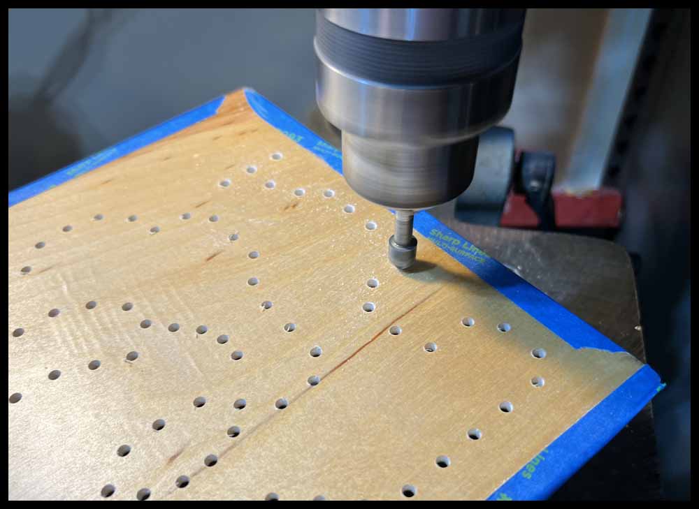
9. Use a small drill bit to drill all the holes through the board. For this example, I used a #48 or .076″ diameter drill bit. The important thing is to drill the holes accurately.
10. Switch to a 3/16″ drill bit and open up all the holes in the board.
11. Flip the board over and use a small countersink and/or sandpaper to deburr the holes. If using a drill press, the easiest way to do this is to hold the board in your hands and lightly press it into the spinning countersink. Do not go deep; just break the sharp edges for appearance.
12. Prepare the image for gluing by using a scrap sheet of paper and your fingers to flatten the pierced holes on the back side. Just press down slightly all over the image where the tiny holes are sticking up.
13. Cover all the holes with small strips of clear tape on the back of the image. This will keep the glue from seeping through in places and making a mess.
14. Use two small pieces of tape to secure the image face down to a piece of scrap poster board or cardboard.


15. Spread glue all over the back of the image. Use a flat foam brush or cardboard to distribute it evenly.
16. CAREFULLY position the image between the tape or locating marks on the wooden board. This can be tricky since it will be heavy with glue. Using a pair of tweezers may help.
17. Place a sheet of paper that is smaller than the image over the top of the image and press down with a paper towel or your fingers to spread the glue out evenly, starting from the center and working towards the edges. (See my comments under the 3rd picture below). Some glue will seep out; wipe it gently with a damp paper towel. Spend some time gently pressing down all over the image until it sets up. Pile some books on top and let the glue dry thoroughly. Only experience will help this task be mastered without a mess. Practicing with some scrap paper first is suggested to determine how much water and pressure the photo paper will stand up to. Good luck! 😉


Make sure the glue is thoroughly dry (overnight) before proceeding with Step 18.
18. Use a 1/8″ tool to partially pierce all the holes from the top. Try to pierce them evenly through the center of the hole made by the push pin in Step 3. Built up glue in the hole may prevent the scribe from going all the way through the board easily. That is okay; just wiggle the scribe around to help the reamer pick up the hole accurately in the next step. (Look at the pictures above in the section on piercing the foam board for a description of the proper tool).
19. Use a 3/16″ reamer to redrill through all the holes. Just carefully center the reamer over the 1/8″ pierced holes in the image and push through. Normally when reaming holes in materials like steel or other metals, the spindle speed used should be rather slow. In this procedure use a higher rpm, up to 1000 rpm. The reamer will cut through the photo paper and then pick up the previously drilled 3/16″ hole. The important points to be mindful of here are: 1. Pierce the holes in Step 18 as close to the center as possible, and 2. Start the reamer carefully over the center. You want the beginning angle on the bottom of the reamer to cut evenly through the paper and then pick up the previously drilled hole without having to move sideways.
There is an alternate method to drilling clearance holes in the board. I personally prefer using the 3/16″ reamer method but this method will work if you cannot find a reamer. In Step 10, drill the holes with a 13/64″ drill bit instead of a 3/16″ bit. Glue the image the same way as shown above. After piercing the holes with the 1/8″ diameter tool in Step 18, use a 3/16″ diameter piercing tool to open up the holes in the image instead of using a reamer as described right above in Step 19. The 13/64″ drill will leave a little room for the extra image paper to be pushed into the hole when piercing with the 3/16″ tool. If the holes looks ragged, clean them up afterwards with any method that works . (How’s that for concise guidance?) 🙂
20. After all the holes have been reamed, use a 3/8″ diameter center punch along with a hammer to smooth the top of each hole. Smack the hammer hard enough to make an angled impression on the top of the hole. It should look similar to a countersunk hole. I prefer this method because using a countersink may tear the photo paper and make a rougher looking hole. (The center punch dimension is not important. It just has to be big enough so that only the angled part will enter the holes.)
There are a few videos below under the section Make a Smaller Version of Rainbow Raceway that show a hole being enlarged after gluing and then being reamed. Another video shows a hammer and centerpnch being used to smooth the tops of the holes. These videos may give a clearer picture of how to ream the holes and use the center punch described in Steps 18-20.
21. This step is optional. The pictures will show how to add some stainless flathead socket screws to make some really cool looking legs.


The board is finished. Touch up any rough spots with sandpaper. As with the foam board above, make some Red Cards and Racecars. Make some eight-sided dice and start racing!
Build a Smaller Version of Rainbow Raceway
To make a smaller version of Rainbow Raceway, choose from the pictures below for the color desired. This version may be convenient for taking on vacation or other situations where a smaller size is desired. However, the bigger version shown above may be more fun for children. Click on the image and save it to a hard drive. Print the image out on glossy photo paper.


Smaller Rainbow Raceway game with a Foam Poster Board base.
To use a foam base for this small version, follow the instructions at the very top of the page. The only differences are that you do not have to assemble two images together, and instead of using 8-32 x 1″ screws to make the racecars, 6-32 x 1″ screws will be used. Therefore, the final hole size pierced in the boards will be closer to 11/64″ instead of 3/16″. Use some calipers to choose a screwdriver or other object such as a drill bottom with a diameter of 11/64″ (.172″) for piercing the holes. Practice on scrap foam poster board first to make sure the fit for the racecars is smooth but not too sloppy.
Smaller Rainbow Raceway game with a Wooden base.


In the picture above my original game is shown on top with some of the plastic Red Cards and tapered dice. Below it are three of the games made on this page, the first with a foam poster board base and the other two with wooden bases. Notice on the green and yellow boards some of the additions that were made in Photoshop. Just for fun, I added initials on the racecars and inserted a picture on the left side of the board.
Click the green button to view and print the directions for Rainbow Raceway from a PDF file.
Red Cards
You will need Red Cards to play the Orbital Summation game. Click on the images below, download them to a hard drive, then print them out on glossy photo paper. Thick card stock will also work, but may not look as nice. There are 16 Happy Faces and 14 Sad Faces.


You have three choices to finish the Red Cards:
1. Cut each card out and use them as is.
2. Cut them out and decorate the blank top side as desired. Any cool design will work.

3. Print out the picture on the right (three copies) and glue them to each image. Spray adhesive works well, but be careful to line them up when doing so. The image on the right has extra “red” around the edges to allow for some mismatch. Let them dry overnight before cutting them out along the outside of the black lines. This will produce a very nice, thick card.

There are several ways to glue the fronts and backs together. The first time I glued the sheets together I used a bottle of tacky craft glue and just laid the sheets on top of one another. This method is shown further down on this page.
Later, I made a mounting fixture out of wood since I have plans for making more cards and numbers in the future. The sheets are laid in place to line them up together. When making the fixture, I carefully screwed three locating edges into position so there was very little slop when an 8 1/2″ x 11″ photo sheet was placed in the fixture.
Some spray adhesives require just one side to be sprayed; others suggest spraying the backs of both pages that will be glued together to make a very strong bond. In these pictures and videos only one side was sprayed. The process goes like this: Place one sheet upside down in the mounting frame. Take the the other sheet and lay it up-side down on a piece of paper towel. Spray lightly with adhesive glue. After spraying, wait 20-30 seconds or so for the glue to get tacky. (This depends on the brand of adhesive spray used.) Carefully pick up the sprayed sheet, flip it upside down, then move it just above the other sheet in the fixture. Start easing the top edge into position, lining the edges together, then allow the top photo sheet to drop onto the other sheet. Take the glued sheets out and move them to a smooth surface such as a counter top. Place the glued sheets on a paper towel, then add another sheet of paper towel on top. Smooth out the glued pieces with pressure from your hands, or use a cheap wallpaper roller. Allow the sheets to dry overnight, then cut out the cards with scissors or a paper cutter. Note: I scrapped several pages before I became a little skilled at the process 🙁 . Maybe practice with a couple of blank sheets first to get a system down that works best for you.
You may notice the 8 1/2″ x 11″ sheets shown above look slightly different than those in the pictures and videos below; I changed the outside design of the cards slightly in 2023.


The method below is the first method I used for gluing sheets together. I switched methods because the system below was slower for me and the glue didn’t always dry correctly. Both methods will work well with practice, however.


Racecars
One way to make game pieces (racecars) easily is to use small machine screws coupled with washers and nuts. For this game I made mine out of 8-32 machine screws 1″ long. For more detail on making Race Cars click the Purple button.
Note: The smaller version of Rainbow raceway will use 6-32 machine screws 1″ long.

Eight-Sided Dice
With some of my other games, I suggest using virtual dice if you cannot find blank dice to make your own. However, this will not work well for small kids. Rolling the dice is part of the thrill, especially for kids playing their first board game.
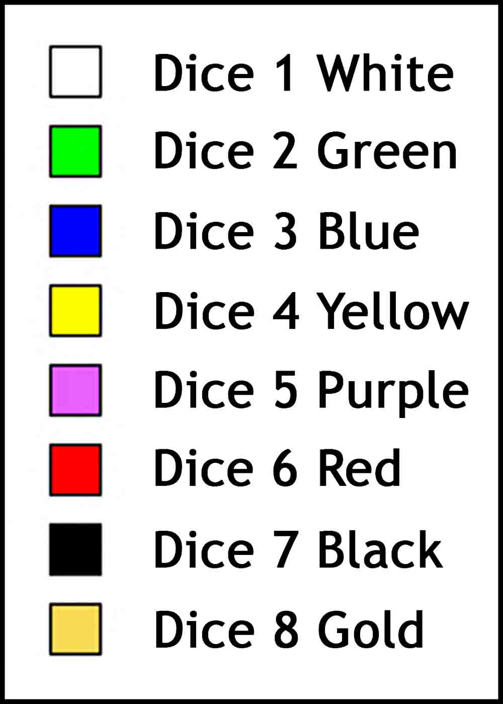
One option is to make some eight-sided dice out of purchased blank dice. Add the numbers 1-8 and color the edges with the corresponding colors as shown below You could also buy some pre-finished eight-sided dice and then add the colors the same way as shown in the second line of pictures below. If you buy pre-finished eight-sided dice, they would have to be white or a light color so the colored edges will be visible after drawing on them with permanent markers.
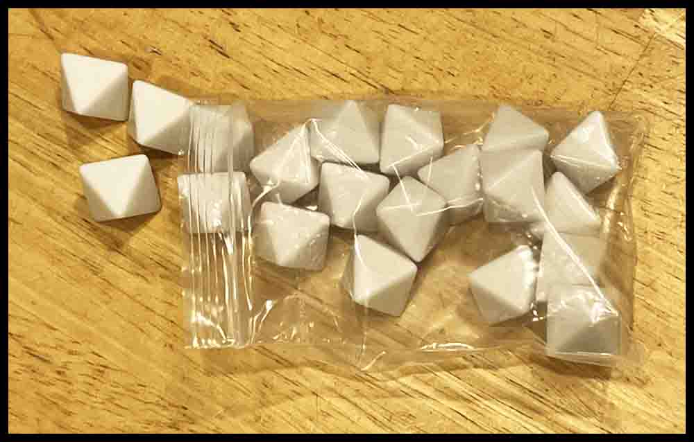


With the pre-finished dice on the left you just need to color the edges.


O C D ? Only watch once!