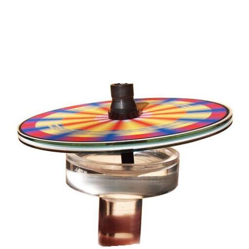
To jump to the bottom section detailing custom made spinner bowls and spindles click here
How to make a simple DynoDisc
The following materials are needed to make a well performing DynoDisc system: 1) Machine screws for the Spindles, 2) Wood, fiberboard, or plastic for the Discs, 3) a soft drink can for the Spinner Bowl.
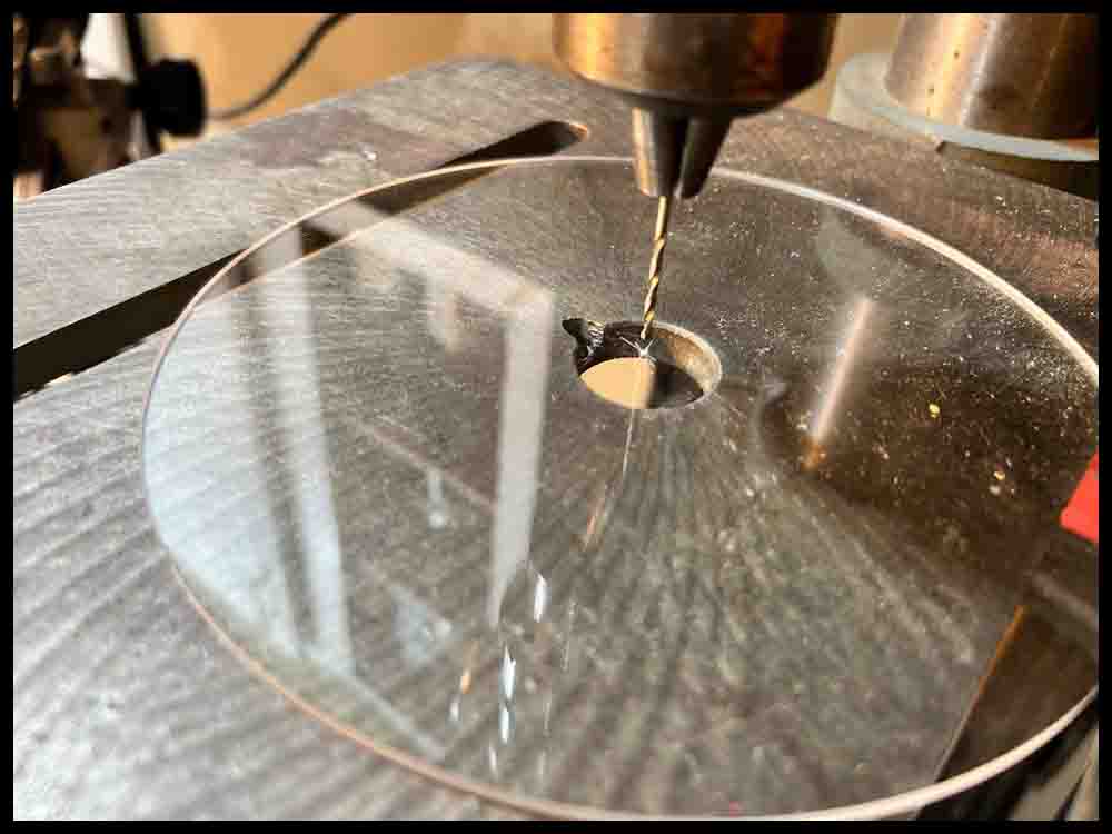
For some of the discs shown here I bought three thin wooden discs online that were a little over 1/8″ thick and precut to diameters of 6″, 8″, and 10″. They worked fine except the 10″ one was warped a bit went it was delivered. The other two discs were also precut and made from an acrylic type of clear plastic with diameters of 7″ and 8″. They made some awesome discs! But you have to be careful drilling the center holes in the plastic; the drill will heat up fast and grab the material easily, possibly breaking the plastic. I drilled mine on my small drill press but you could use a hand drill.
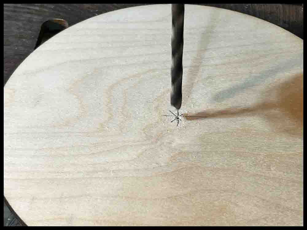
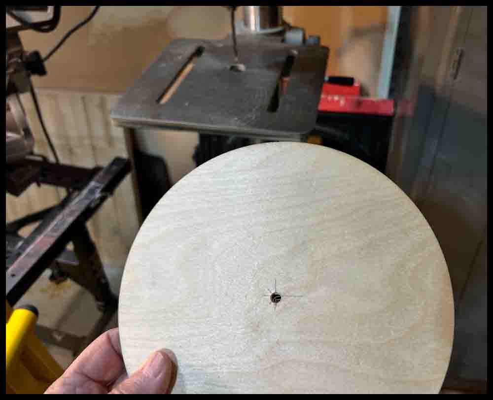
After obtaining the material you will use for the discs, drill a 1/4″ or 5/16″ hole in the center depending on what size screw you will be using for the spindles (see below). You have to be very precise in finding the center of your precut disc before drilling the clearance hole. The more the hole is off center, the more wobble you will encounter. I will show how I drilled mine below in pictures.
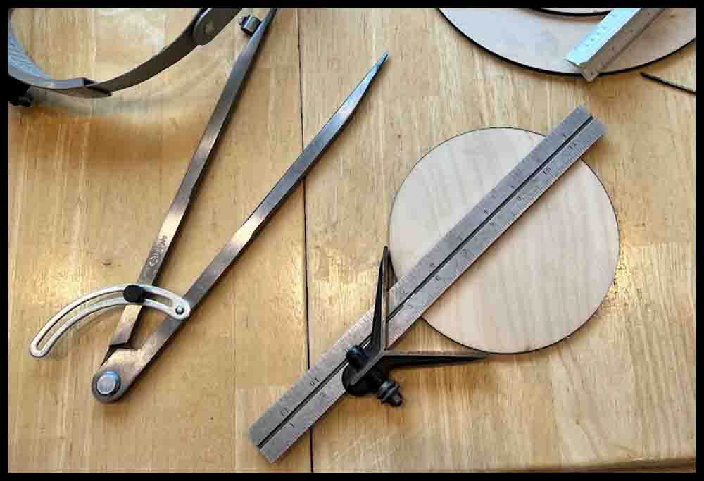
If you do not buy pre-cut plastic or wood, then use a compass like the one in the first picture to lay out a circle. Make a prick with the center punch in the middle and then draw the circle. You will be able to bypass the first steps shown below where the exact center is marked for drilling. After drawing the circle on the material you are using, use a saw to cut it out. Smooth all the edges.
Be sure to zoom in on the pictures by clicking on them. Watch the videos in fullscreen by clicking the small square in the video controls.
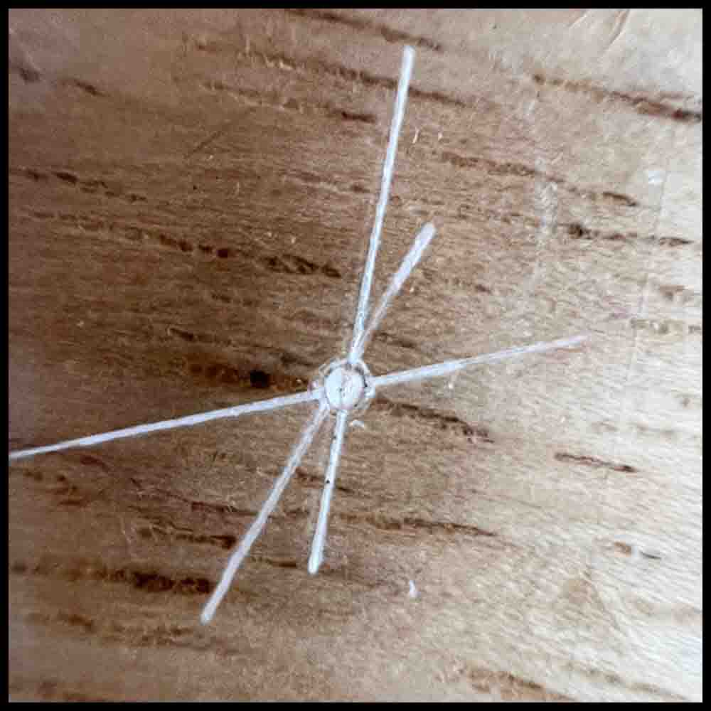
The easiest way to find the center of the precut discs is to use a combination square set and make 3 or 4 marks to establish the center location. Carefully use a center punch and make a small prick mark. Use a ruler to check from different angles for the accuracy of the center prick. Adjust as necessary.

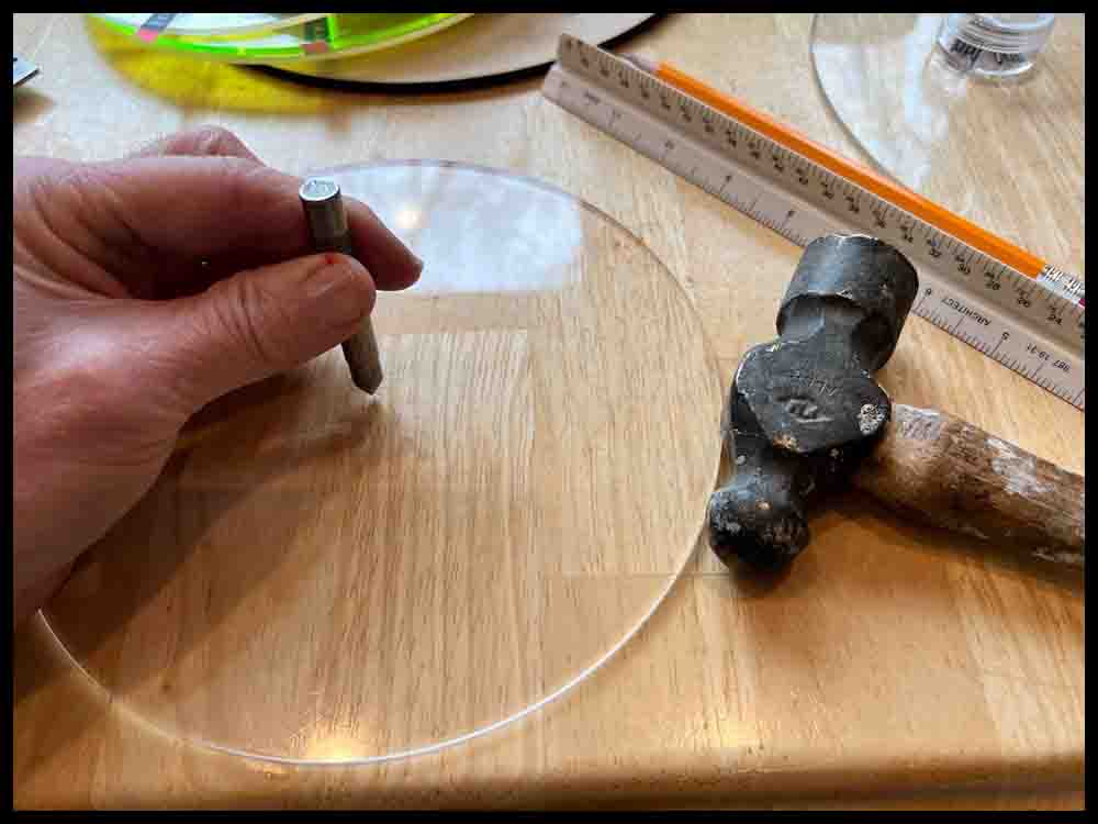
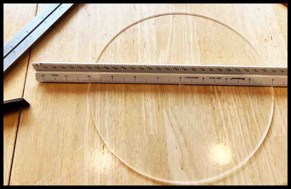
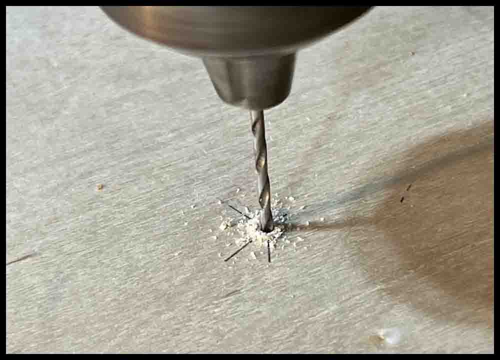
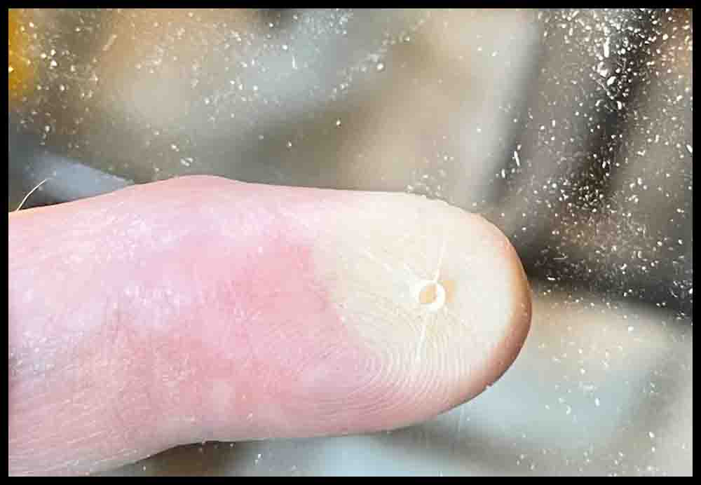
These four pictures show the process used in drilling the plastic and wooden discs. If you are using a drill press, make sure to line up the drill closely before turning on the spindle.
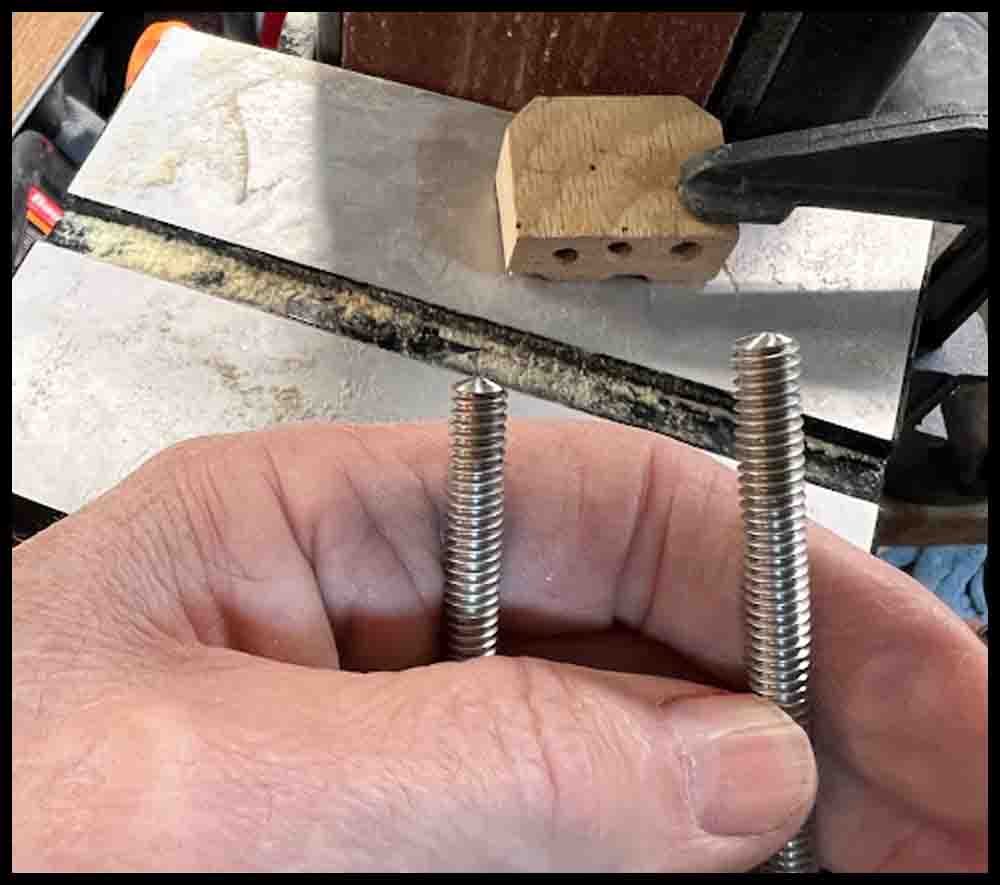
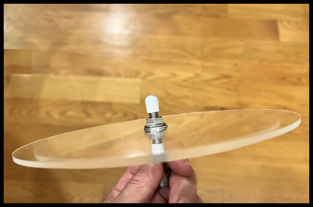
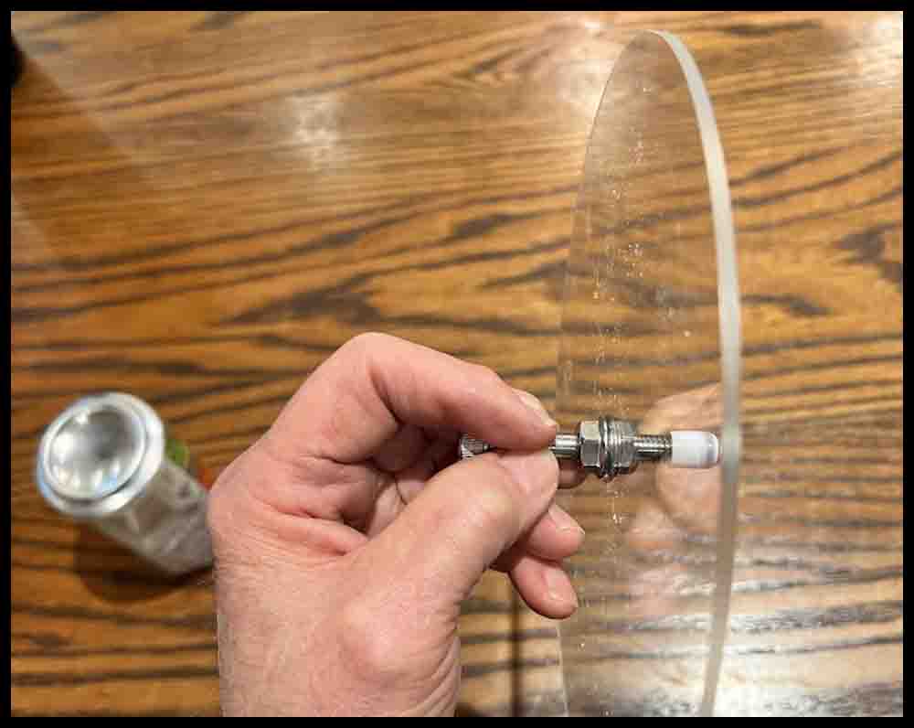
For the spindles I made in this demo I used both 2″ and 2 1/2″ long 1/4 – 20 Hex Head Screws and some 5/16-18 socket head cap screws, all stainless steel. However, regular machine screws made out of softer steel will work fine. Get some nuts and washers that fit the screws to secure the discs to the spindle. I also cut off a piece of 3/8″ ID clear rubber tubing and pressed it onto the top of the 5/16″ socket head cap screw. It makes it easier to grasp when spinning the disc.
The easiest way to make a smooth spinning tip for the bottom of the screw is to buy some rubber end pieces found in a hardware store that go on wire shelving. Pick the right size for the spindle being made. The most common sizes slip on 1/4″ and 5/16″ machine screws perfectly.
The rubber tips will make a working point that will also grip the spinner bowl. Just slip them off and on when changing or adding discs to the spindle.
If you have a belt sander you may want to grind an angle on the screw bottom. That will make the rubber tip be a little firmer where it makes contact with the can or spinner bowl.
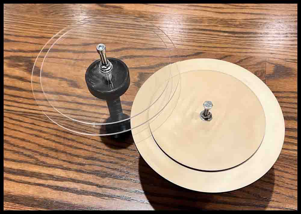
The following pictures show how to make different designs on cardstock or paper to add on top of the finished discs.
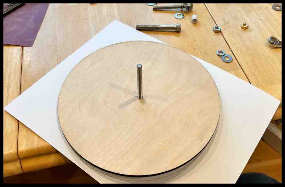
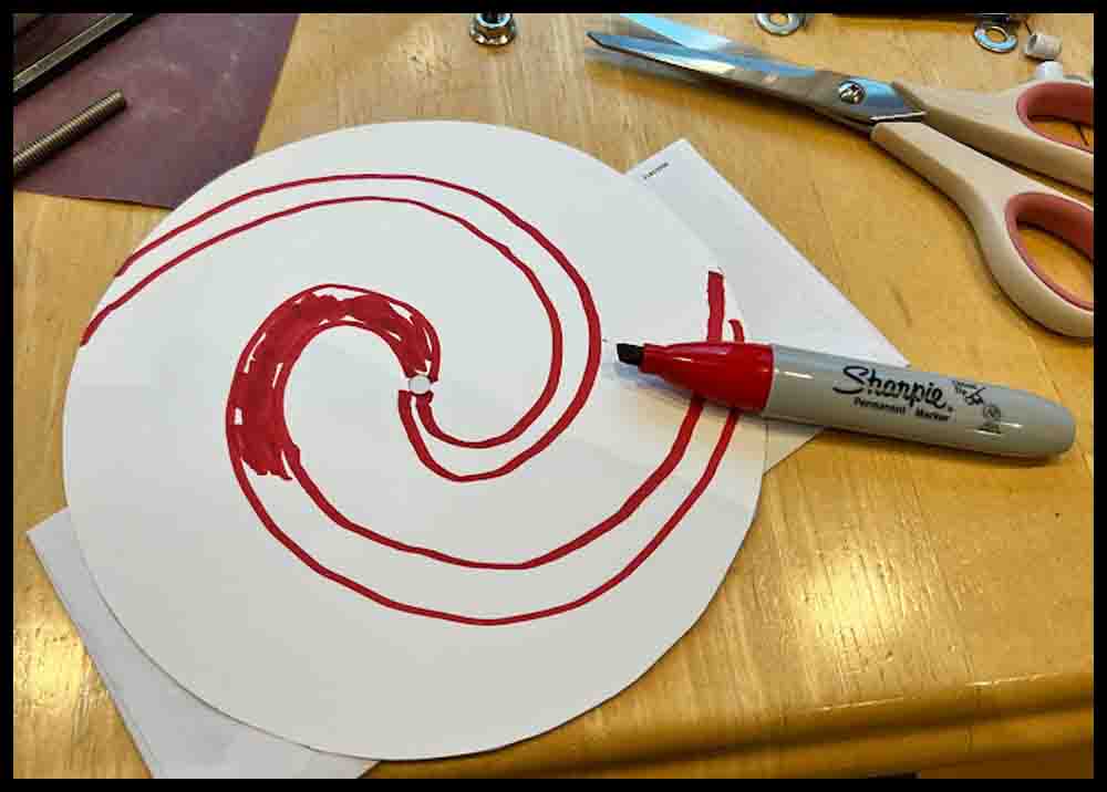

More designs
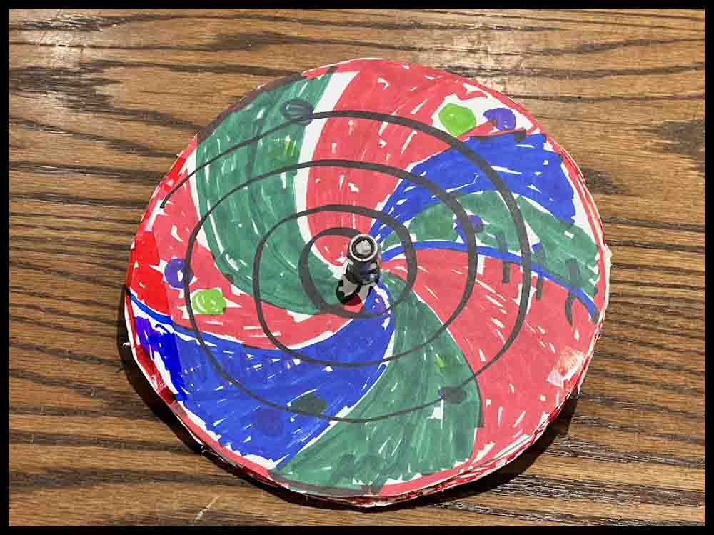
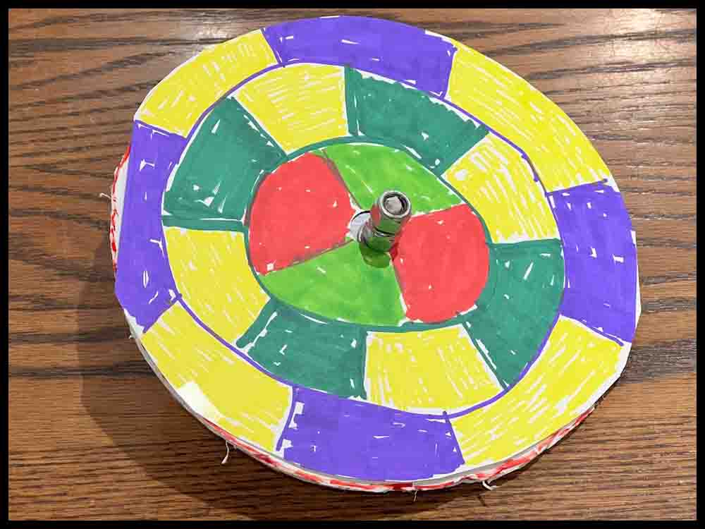
DynoDisc spinning instructions are shown below.
The two images on the right are practice pads for use when learning to spin a DynoDisc. Click on them, save to a hard drive, then print them out on some heavy cardstock.
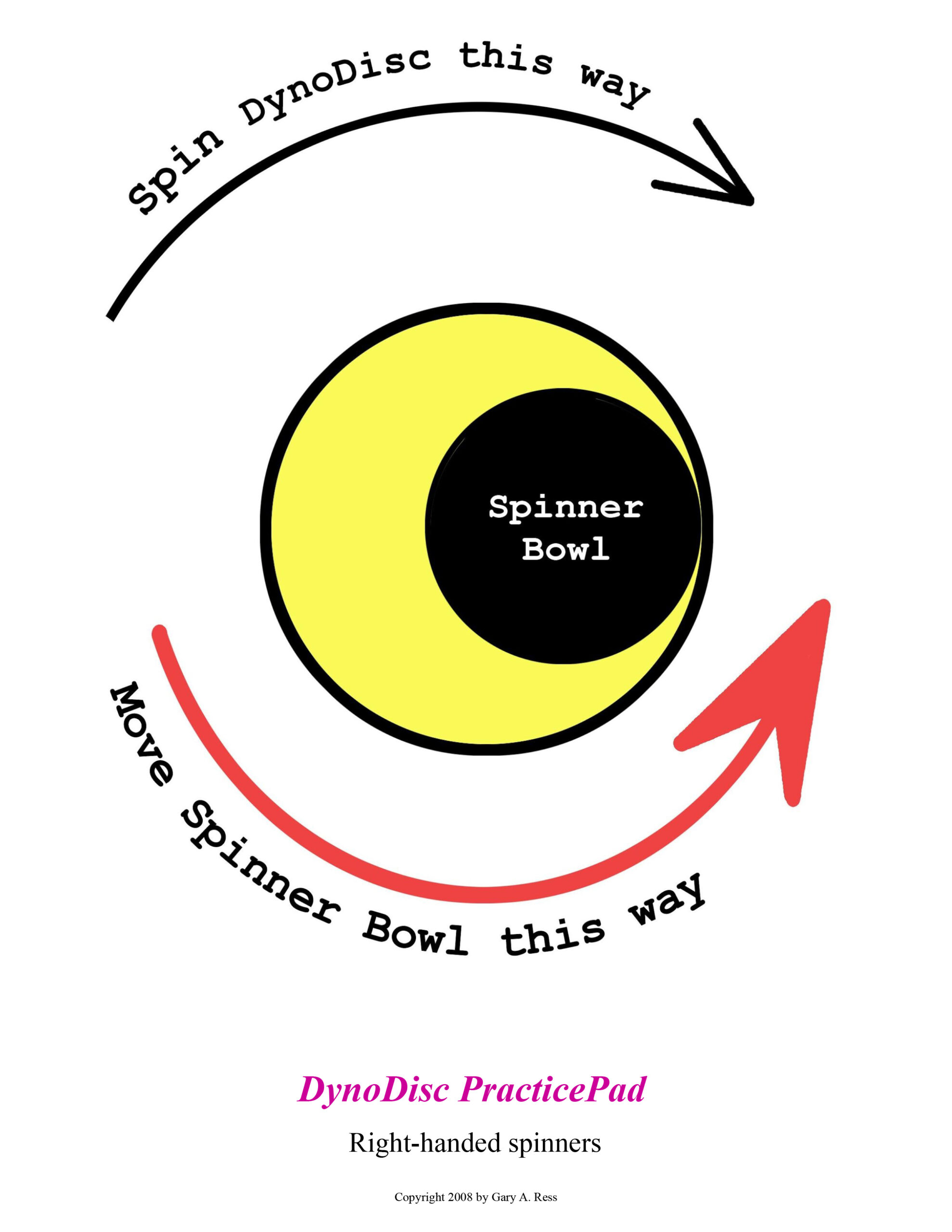
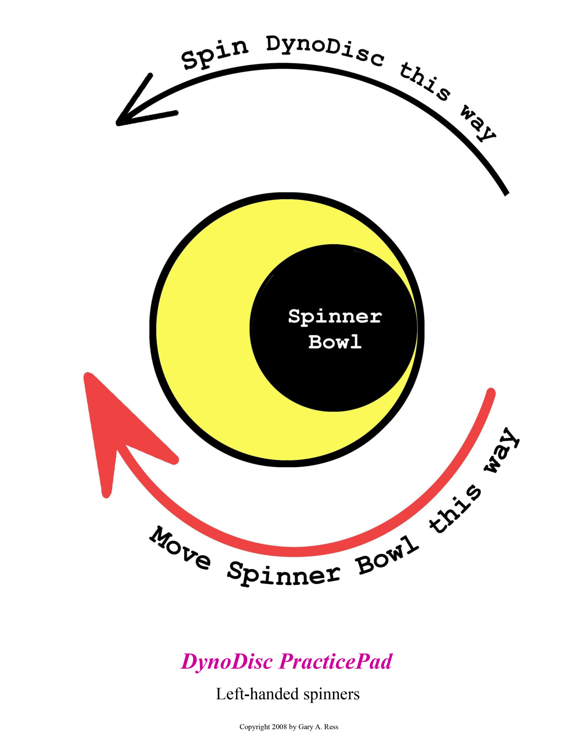
Custom Made Spindles and Spinner Bowls
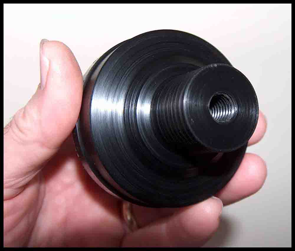
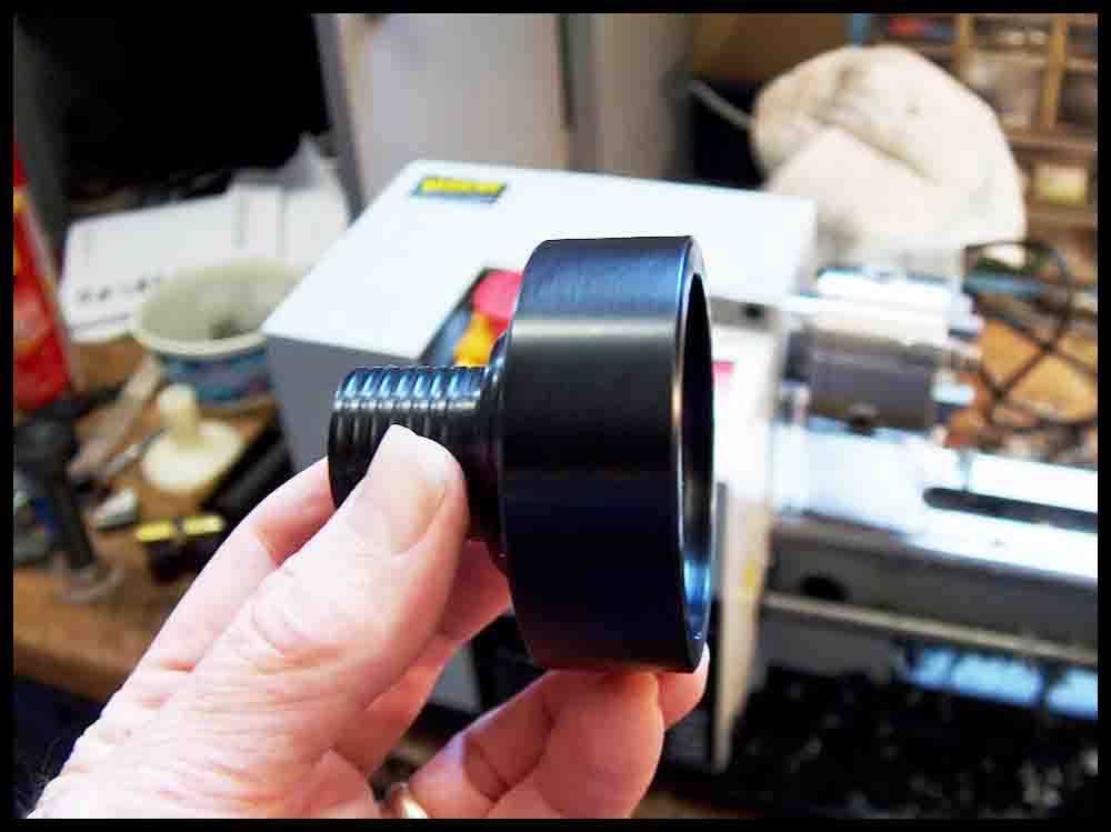
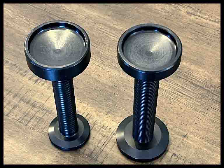
A custom made spinner bowl will work a lot better than the bottom of a soft drink can when it comes to spinning a DynoDisc. Combined with a custom made spindle, the discs will spin very smoothly and accelerate quickly. In both slideshows there are comments written on the bottom left of the pictures.
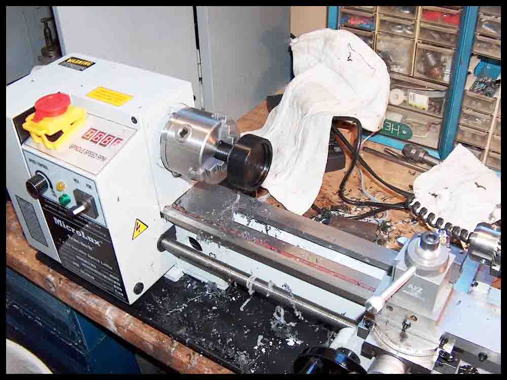
The slideshow below shows how a spinner bowl was made in the lathe.
Blueprints for a typical spinner bowl and spindle.


In the upper right corner of the blueprint of the spindle on the left is cutaway “AA”. Notice the little recess at the bottom of the drilled hole. This feature was drilled in picture #5 in the slideshow below. A center drill was used to make the small recess at the bottom of the drilled hole. When stacking, the extra clearance insures that the bottom of the top disc spindle will make good contact with the 20 degree angle. The reason for this is explained in the paragraph below the blueprint.
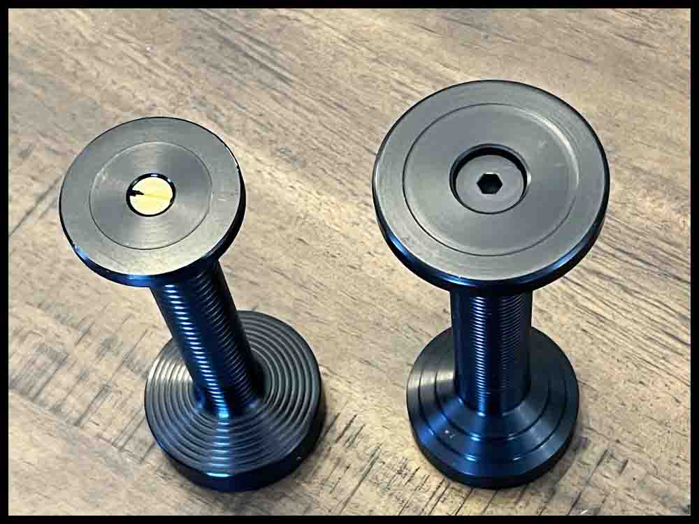
The diameter of .591 will fit easily into a CD or DVD opening. Since the thread itself is a 5/8″-18 thread (outside diameter .625), there is plenty of slop when the nut is screwed on. It will still secure the discs tightly. The bottom of the spindle will vary in the final shape to give the spindle a one-of-a-kind look. The only semi-critical dimension is the bottom 3/8″ or so of the spindle shaft. The shaft has to fit easily into a .350 hole when stacking a disc on top of another. Plus if the diameter is too small it will make it harder for the disc to accelerate without excessive slippage. The O-Ring helps the spindle grip the side of the spinner bowl. The nut, not shown, also has O-Rings to give a DynoDisc spinner some extra grip.
This slideshow below details the making of a typical spindle.

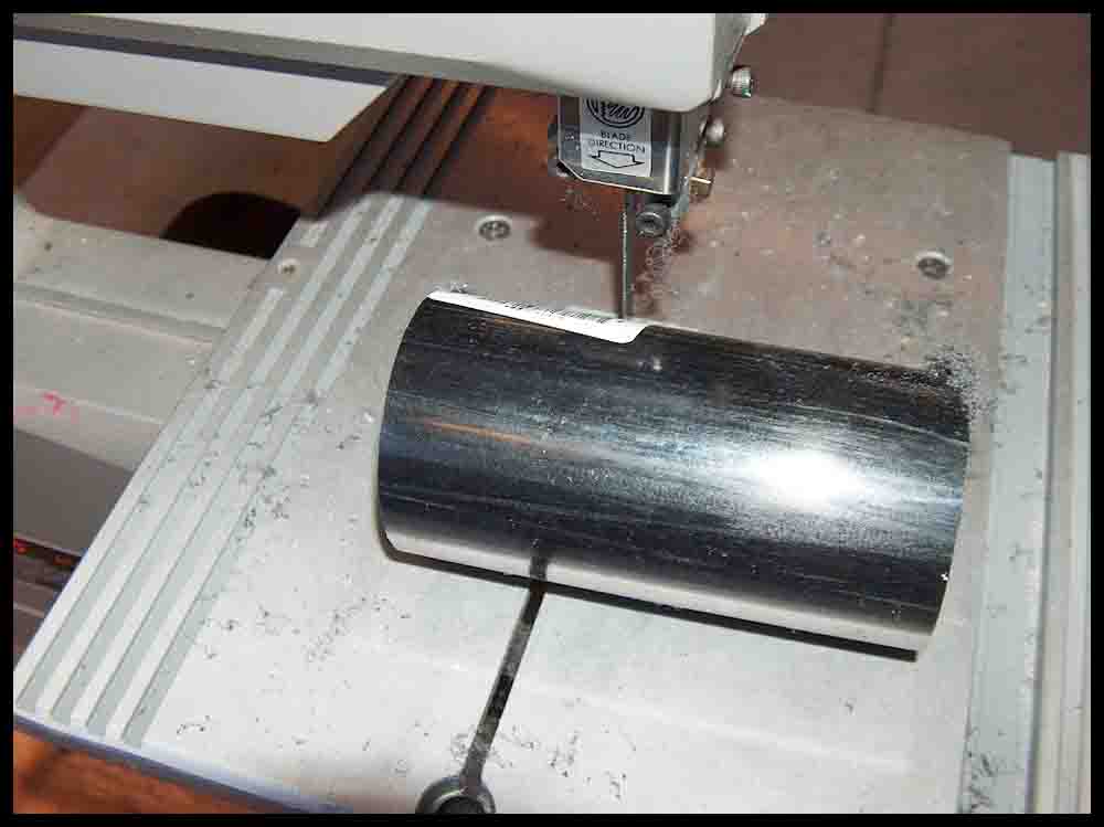
1″ diameter Black Acetyl being cut to length. 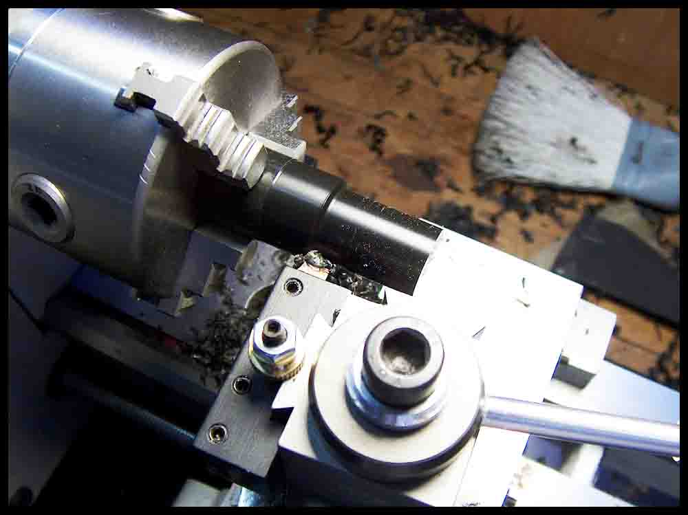
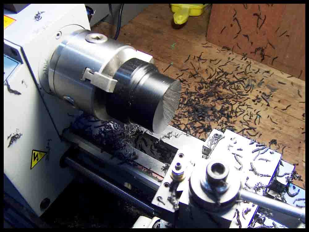
Turning the diameter that will become the threaded portion on top. 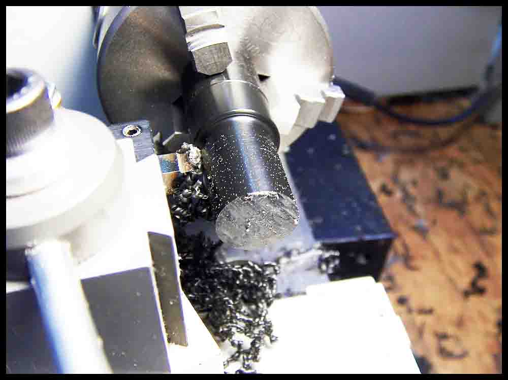
Acetyl is a dream to machine. 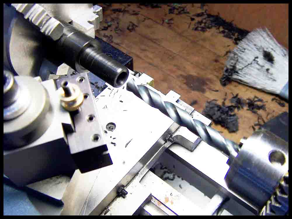
Drilling out the top of the spindle with an “S” drill. 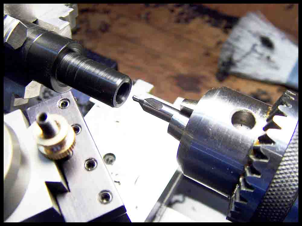
A center drill is used to add a recess in the bottom of the drilled hole. 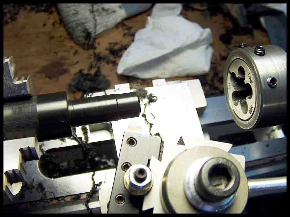
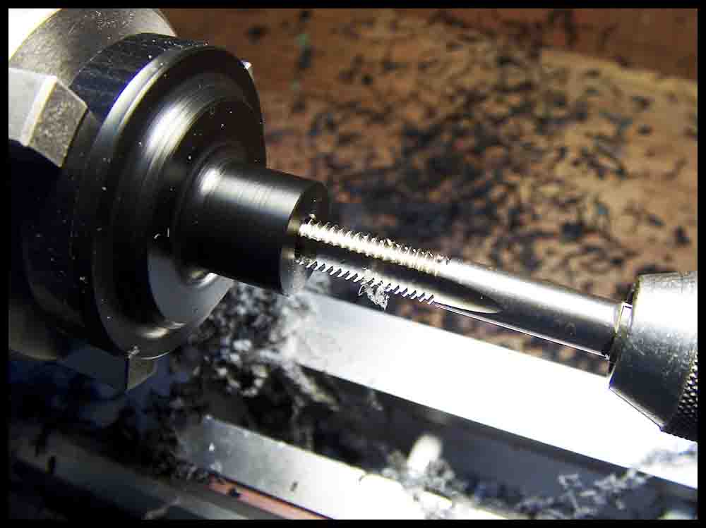
Preparing to start the initial cut of the 5/8-18 thread. 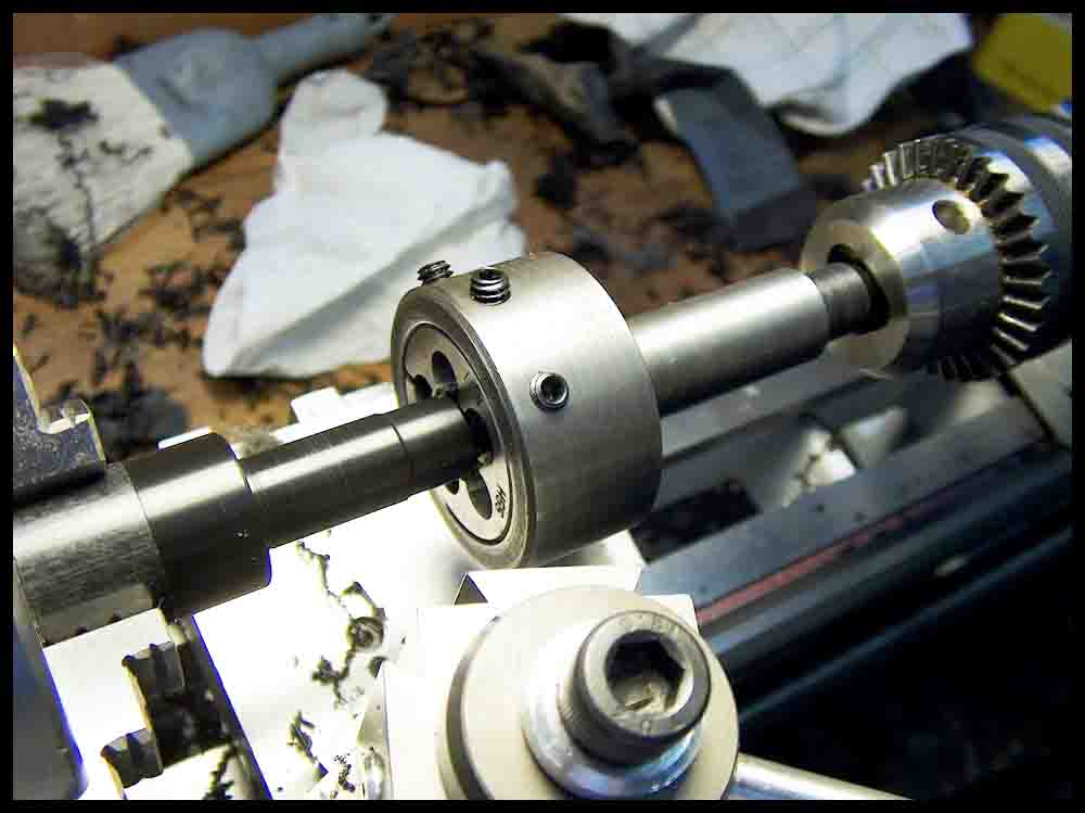
The die holder was custom made for this job. 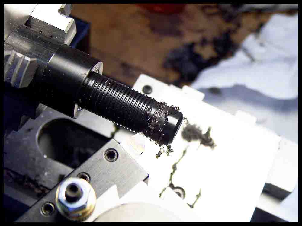
First pass finished for threads. 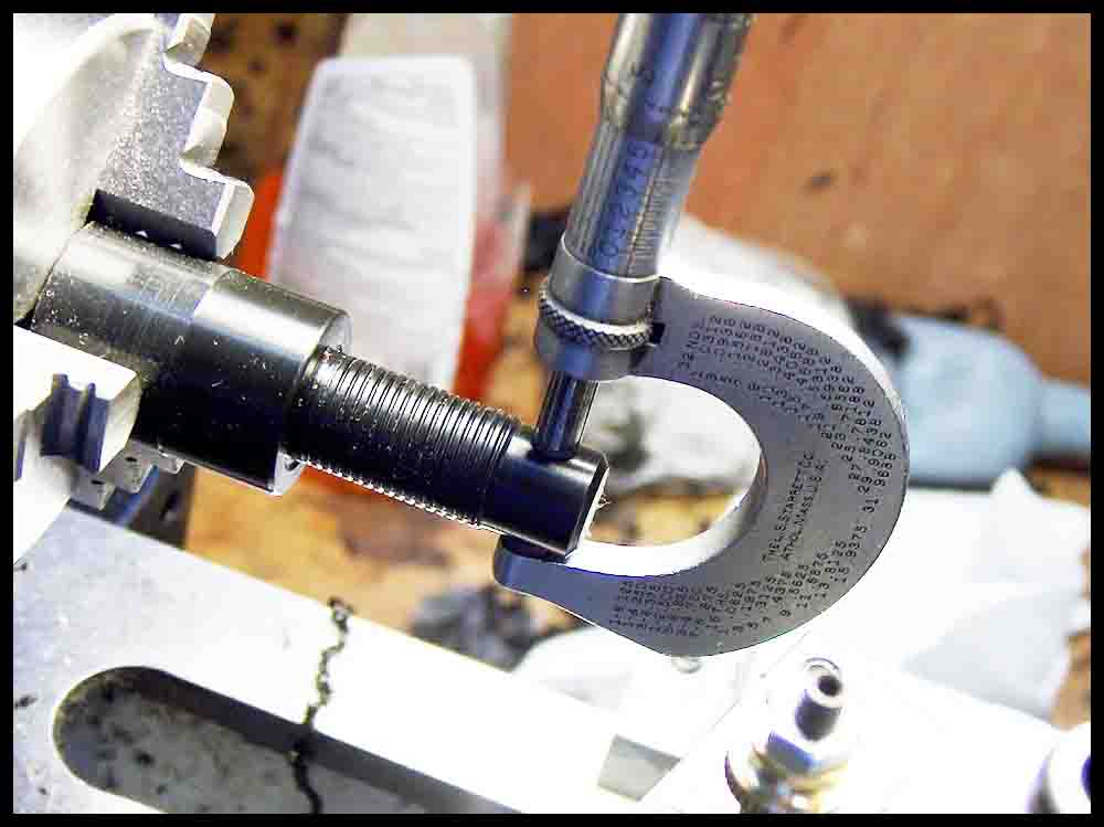
Checking dimensions. 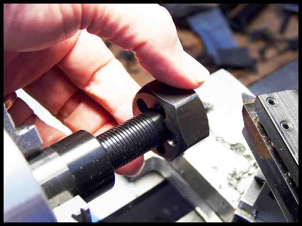
This finishing die will make the final cut on the thread. 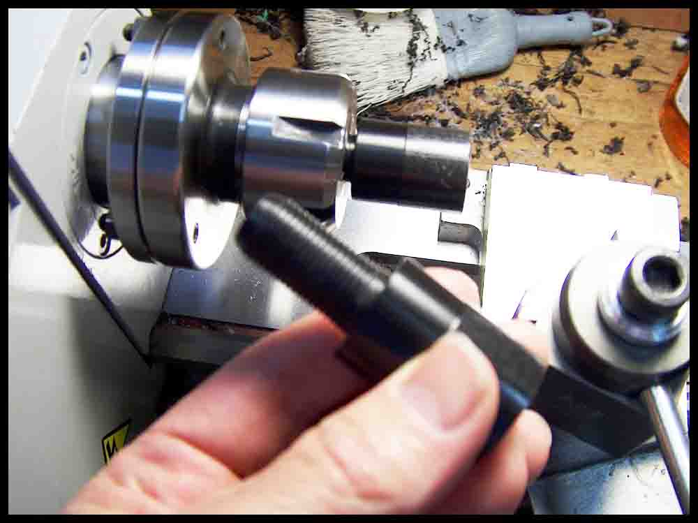
The part is removed and turned around to cut the bottom half of the spindle. 
Initial cuts. 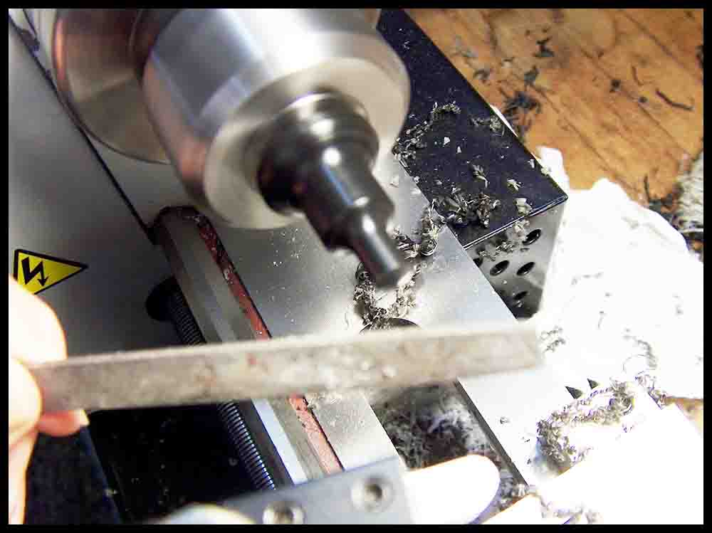
Bottom angle finished. 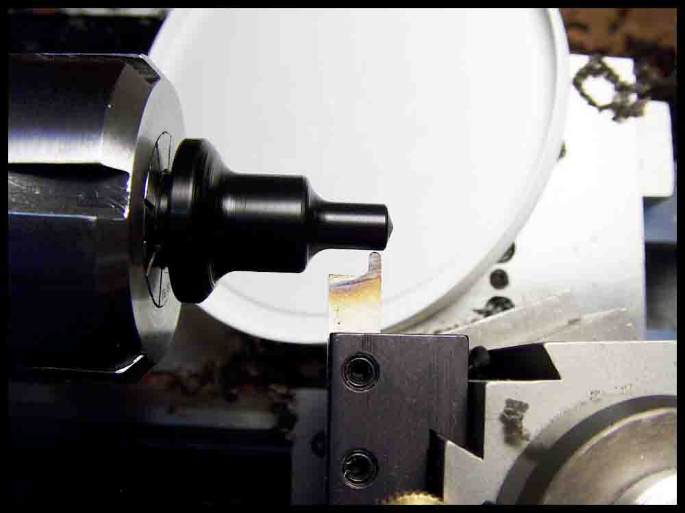
Getting ready to cut the O-Ring groove. 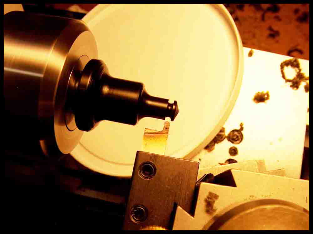
O-Ring groove finished. 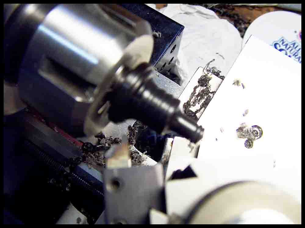
O-Ring installed in groove. 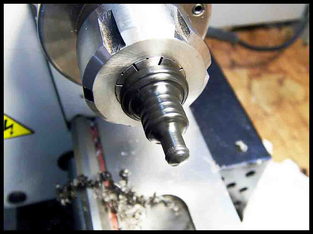
All finished! 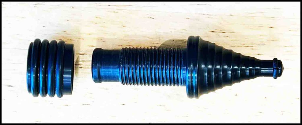
This is another finished spindle with the accompanying nut.


P i c k y o u r p o i s o n !
C l i c k , S a v e , P r i n t , a n d D r a w.
.